Data model of participation in multi-channel and multi-party contacts

a data model and multi-channel technology, applied in the field of contact center management, can solve the problems of not supporting multi-channel contacts, unable to record, and existing data warehouse models in the data warehousing industry provide, at most, only limited information on contacts, etc., to achieve accurate multi-party tracking, less detail, and effective and/or inexpensive

Active Publication Date: 2011-05-31
AVAYA INC
View PDF415 Cites 46 Cited by
  • Summary
  • Abstract
  • Description
  • Claims
  • Application Information

AI Technical Summary

Benefits of technology

[0015]A “contact part” represents a single party, contact state and / or communication channel in a contact or communication session. Typically, the contact part is based collectively on a single party, contact state, and channel. A contact part can thus be the smallest measurable part of a communication. Typically, a new contact part is created, and a prior contact part terminated, whenever a monitored party and / or channel is added or dropped and / or experiences a state change. In contrast, the contact maintains its identification throughout its lifetime, regardless of the number of parties and channels that are involved. At least one (and probably more) contact part(s) is / are created for every party / endpoint in the contact, including customers, agents, automated resources, and any other entity that participates in the contact. In other words, each endpoint to the contact or communication session is commonly monitored independently and separately. Thus, a first endpoint in a communication session can have a first contact part and a second endpoint in the same communication session can have a second contact part that temporally overlaps the first contact part. The use of a contact part can allow tracking the time that each party in the contact spends communicating and on hold (or the equivalent) as well as providing the complete picture of who joined the contact, at what point, and for how long.
[0017]The present invention can provide a number of advantages over the prior art. For example, the contact part provides a complete and detailed record of all states, participants, and channels involved in a given contact from the time the contact reaches or is launched by a contact center until it is terminated. The contact part and related entities thus allow accurate and detailed reporting of complex interactions with regard to the involvement of each party and communication channel. Examples of such contacts include conference calls where parties join and leave the conference during the course of the contact and voice chat sessions where parties add and drop the voice channel to an existing Web chat. As noted, conventional architectures generally provide either summary reporting (such as the number of times an agent held a call) or detailed reporting only on certain parties involved in such interactions. The prior does not track multi-party contacts. Additionally, the present invention can support reporting at higher levels with less detail that may be more comprehensible to users of reports than the low-level detail captured. The ability to accurately track multi-party and multi-channel contacts can enable contact center administrators and managers to identify not only more effective and / or inexpensive ways to service customer contacts but also more effective ways to manage limited contact center resources.

Problems solved by technology

However, CMS does not record when the call was put on hold by which participants and when the call was removed from hold by each party.
The data model does not support tracking for conferences involving multiple external parties nor for multi-channel contacts.
Finally, existing data warehouse models in the data warehousing industry provide, at most, only limited information on contacts.
Existing models tend to focus on customer and billing information from sales and marketing systems but typically do not contain structures that support interaction details.
The models fail to provide the granular details that will allow contact centers to analyze the details of individual contacts.

Method used


Image

  • Data model of participation in multi-channel and multi-party contacts
  • Data model of participation in multi-channel and multi-party contacts
  • Data model of participation in multi-channel and multi-party contacts

Examples


Embodiment Construction

[0026]The invention will be illustrated below in conjunction with an exemplary communication system. Although well suited for use with, e.g., a system having an ACD or other similar contact processing switch, the invention is not limited to use with any particular type of communication system switch or configuration of system elements. Those skilled in the art will recognize that the disclosed techniques may be used in any communication application in which it is desirable to provide improved contact processing.

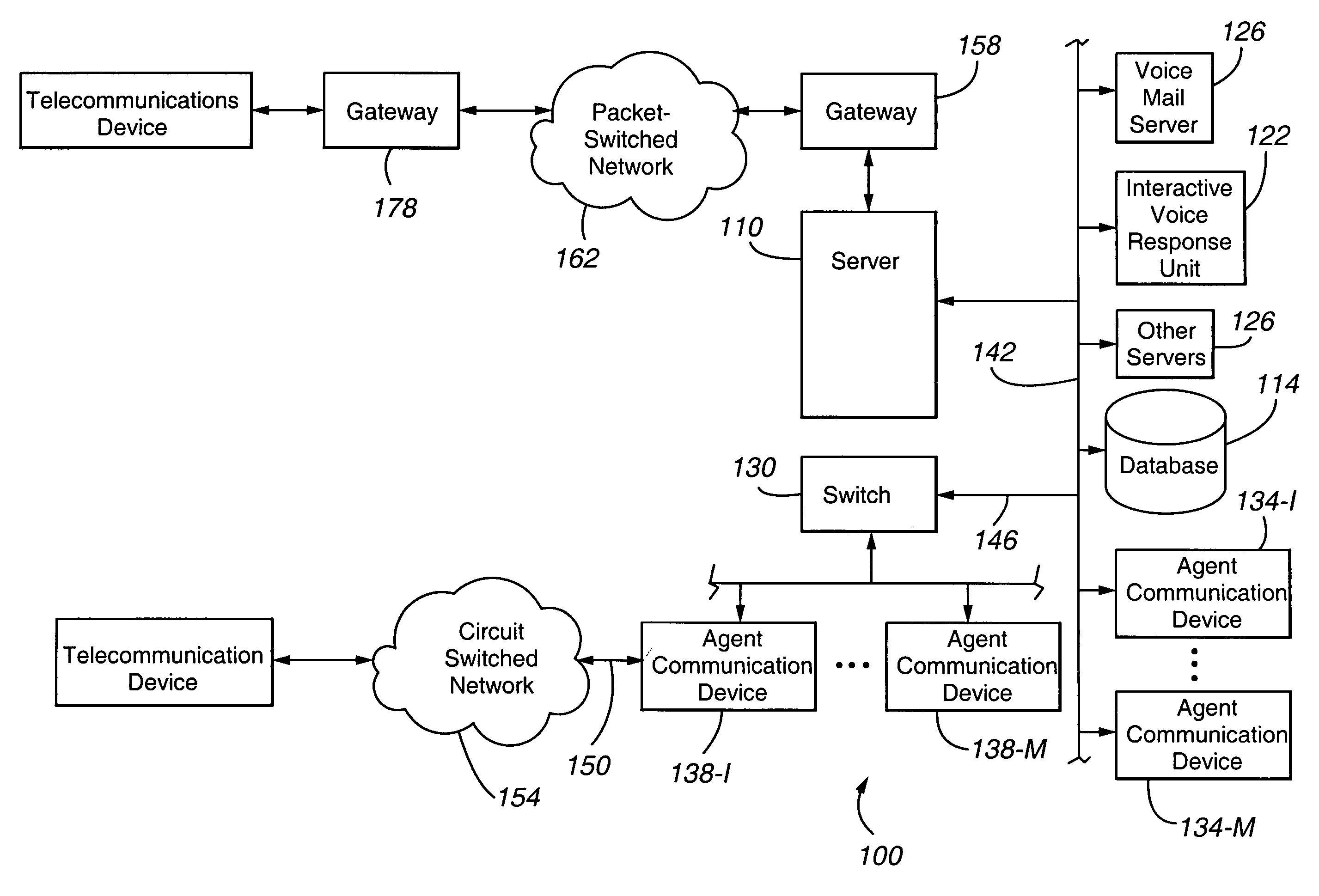
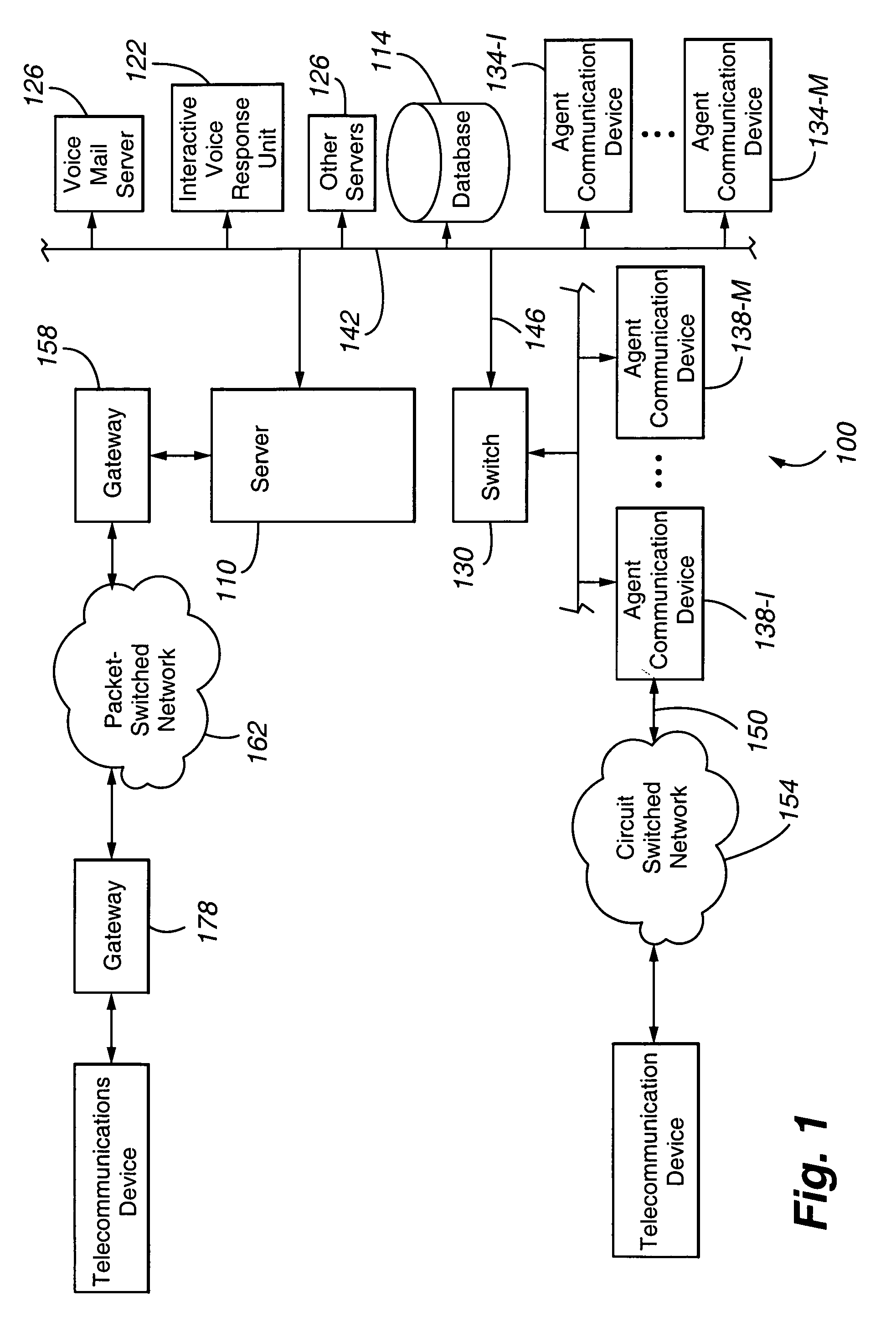
[0027]FIG. 1 shows an illustrative embodiment of the present invention. A contact center 100 comprises a central server 110, a set of data stores or databases 114 containing contact or customer related information and other information that can enhance the value and efficiency of the contact processing, and a plurality of servers, namely a voice mail server 118, an Interactive Voice Response unit or IVR 122, and other servers 126, a switch 130, a plurality of working agents o...


PUM


Abstract

The present invention is directed to a contact center that includes a switching fabric 110, 130 operable to configure a communication session between a first customer and a first resource 138 for servicing of a first contact by the first resource and a contact tracking agent 232 operable, during the servicing of the first contact by the first resource, to (a) monitor the first contact center endpoint for at least one of (i) a change in contact state, (ii) the connection of the first resource and the first customer through a second (new) communication channel, and (iii) the addition of a party to and / or removal of a party from the communication session and (b), when the at least one of (i)-(iii) occurs, terminate a first contact part and create a second contact part. The first and second contact parts are associated with the communication session.

Description

CROSS-REFERENCE TO RELATED APPLICATION[0001]This application claims the benefits under 35 U.S.C. §119 of U.S. Provisional Patent Application Ser. No. 60 / 558,613, filed Mar. 31, 2004, of the same title and to the same inventors, which is incorporated herein by this reference.FIELD OF THE INVENTION[0002]The present invention is directed generally to contact center management and specifically to monitoring selected contact center events.BACKGROUND OF THE INVENTION[0003]Contact centers, such as Automatic Call Distribution or ACD systems, are employed by many enterprises to service customer contacts. A typical contact center includes a switch and / or server to receive and route incoming packet-switched and / or circuit-switched contacts and one or more resources, such as human agents and automated resources (e.g., Interactive Voice Response (IVR) units), to service the incoming contacts. Contact centers distribute contacts, whether inbound or outbound, for servicing to any suitable resource...

Claims


Application Information

Patent Timeline
Patent Type & Authority Patents(United States)
IPC IPC(8): G06F15/16G06F17/00
CPCH04M3/5191H04M3/5175
Inventor KIEFHABER, SARAH HILDEBRANDTSNYDER, ROBERT W.TAYLOR, ROBIN DONALDZANONI, DAVID
Owner AVAYA INC
Why Eureka
Try Eureka