
Muzzle brake

a technology of muzzle brake and muzzle, which is applied in the direction of muzzle attachment, weapon components, weapons, etc., can solve the problems of reducing combat effectiveness and other known muzzle brakes effectively compensating for concussion, and achieve the effect of reducing concussion

Active Publication Date: 2011-06-07
SUREFIRE LLC
View PDF24 Cites 19 Cited by
  • Summary
  • Abstract
  • Description
  • Claims
  • Application Information

AI Technical Summary

Benefits of technology

The present invention is a muzzle brake for firearms that reduces concussion to the shooter and reduces the movement of the firearm's muzzle upon firing. It includes a cylindrical body with an axial passageway and two chambers for receiving combustion gases from the muzzle. The chambers have a forward wall for deflecting gases and at least one gas diverting surface to direct the flow of gases. The muzzle brake also includes at least one port for venting a portion of the gases in the first chamber to counter upward and sideward movement of the muzzle. The technical effects of the invention include reducing concussion and improving firearm accuracy.

Problems solved by technology

Many such muzzle brakes, when used in a combat situation, tend to direct concussion from combustion gases back to the shooter and personnel to the side of the shooter at a level that detracts from combat effectiveness.
Further, it does not appear that these and other known muzzle brakes have effectively compensated for muzzle rise (i.e. upward movement of the muzzle) or sideward movement of the muzzle upon firing of the firearm, particularly as concerning sideward movement to the right for a right-hand shooter and to the left for a left-hand shooter.

Method used


Image

  • Muzzle brake
  • Muzzle brake
  • Muzzle brake

Examples


Embodiment Construction

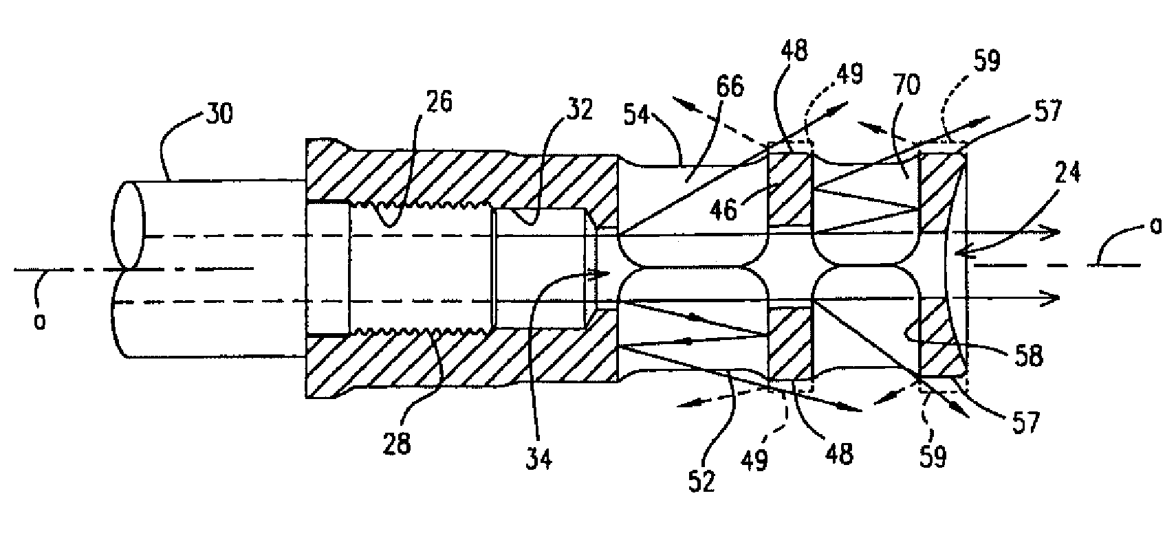
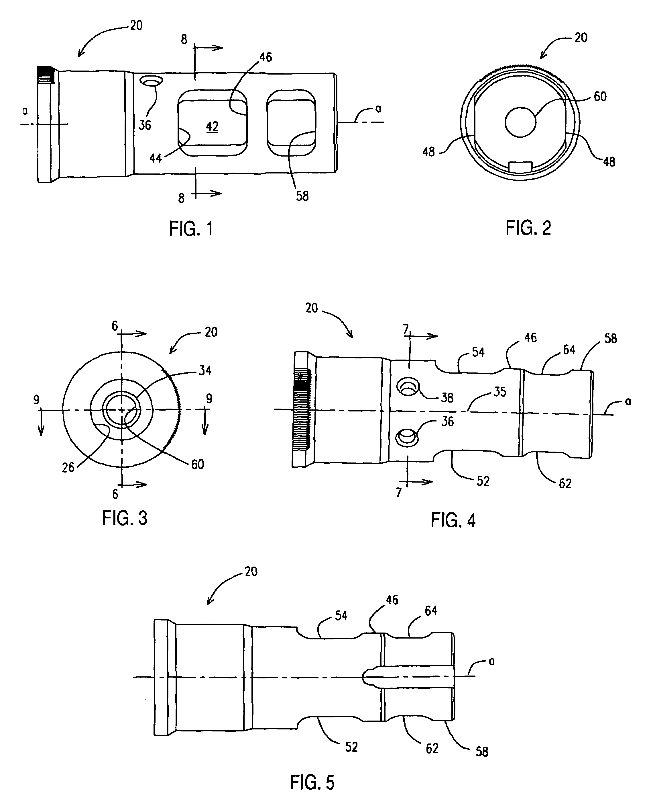
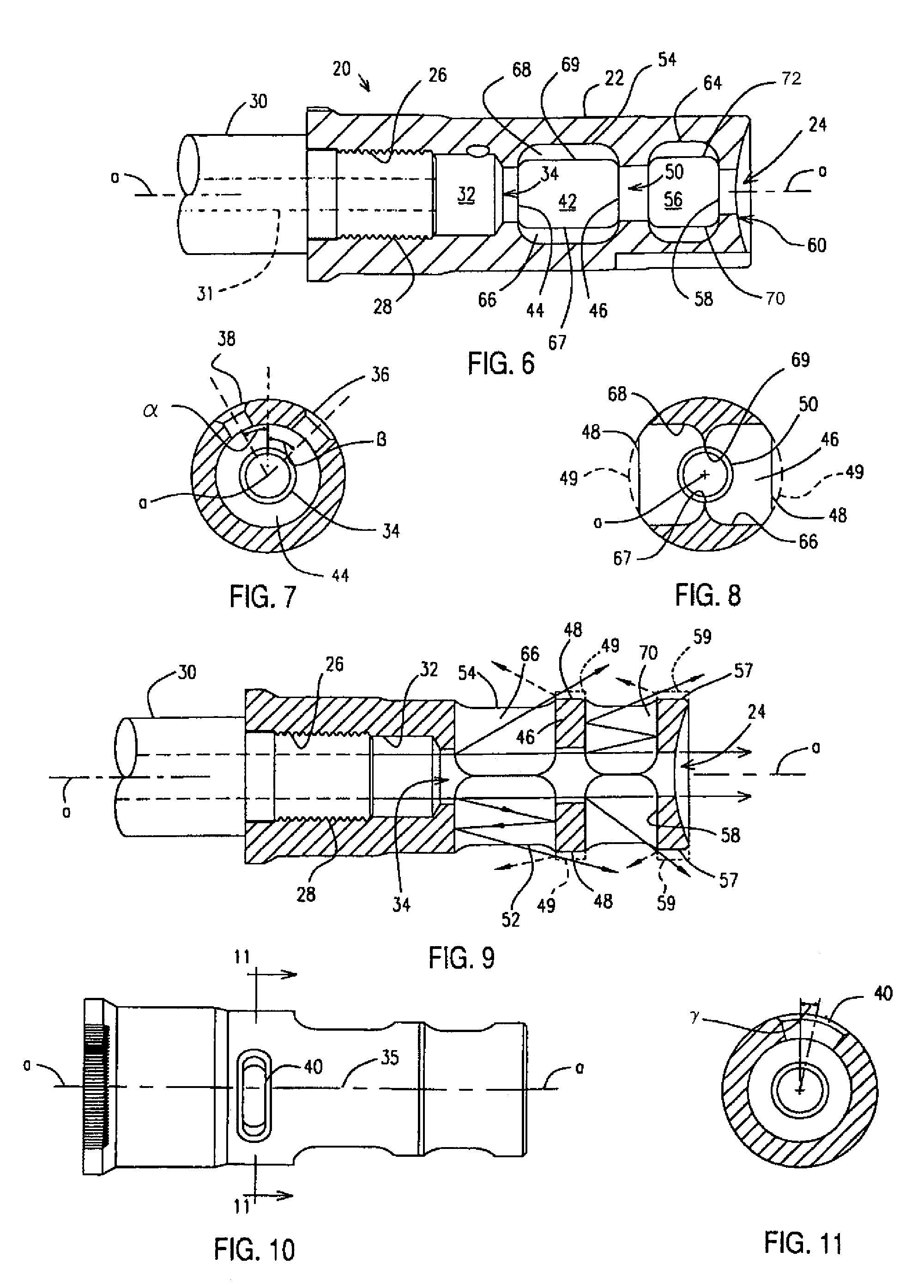
[0022]Turning to the drawings, there is illustrated in FIGS. 1-9 a preferred embodiment of a muzzle brake 20 comprising a generally cylindrical body 22 having an axial passageway 24 forwardly of and communicating with a threaded bore 26 for threadedly securing the muzzle brake 20 to the threaded muzzle 28 of a firearm barrel 30 (see, in particular FIGS. 6 and 9). When the firearm is fired by a shooter, a bullet travels along the longitudinal bore 31 of the barrel 30, along the axial passageway 24 of the secured muzzle brake 20, and exits through an exit bore 60 at the muzzle brake's front end.

[0023]As used herein, the word “front” or “forward” corresponds to the firing direction of the firearm represented by the firearm barrel 30 (i.e., to the right as shown in FIGS. 1, 4-6, 9 and 10); “rear” or “rearward” corresponds generally to the direction opposite the front or forward direction; “longitudinal” means the direction along or parallel to the longitudinal axis a of the muzzle brake...


PUM

PropertyMeasurementUnit
diameteraaaaaaaaaa
pressureaaaaaaaaaa
transverse distanceaaaaaaaaaa

Abstract

A muzzle brake for a firearm, the muzzle brake including structural features that affect the flow characteristics of the combustion gases for reducing concussion to the shooter and to personnel to the sides of the shooter, as well as for directionally countering upward and sideward movement of the firearm's muzzle upon the firing of the firearm.

Description

BACKGROUND OF THE INVENTION[0001]This invention relates to muzzle brakes for firearms, and more particularly to a muzzle brake with improved combat effectiveness.[0002]Muzzle brakes for firearms typically include various baffles, ports and vents to reduce recoil and muzzle rise when firing the firearm. Many such muzzle brakes, when used in a combat situation, tend to direct concussion from combustion gases back to the shooter and personnel to the side of the shooter at a level that detracts from combat effectiveness. Further, it does not appear that these and other known muzzle brakes have effectively compensated for muzzle rise (i.e. upward movement of the muzzle) or sideward movement of the muzzle upon firing of the firearm, particularly as concerning sideward movement to the right for a right-hand shooter and to the left for a left-hand shooter.SUMMARY OF THE INVENTION[0003]The muzzle brake of the present invention includes structural features that affect the flow characteristics...

Claims


Application Information

Patent Timeline
Patent Type & Authority Patents(United States)
IPC IPC(8): F41A21/00
CPCF41A21/36Y10T29/49826
Inventor DUECK, BARRY W.VOIGT, MICHAEL
Owner SUREFIRE LLC
Learn More