Shorting clip terminal connector assembly including protrusion shield

a technology of connector assembly and shorting clip, which is applied in the direction of connection, electrical apparatus, coupling device connection, etc., can solve the problems of replacing damaged components, incurring further undesired concomitant damage within the cavity of the housing, and affecting the service life of the shorting clip terminal

Active Publication Date: 2011-06-07
APTIV TECH LTD
View PDF23 Cites 37 Cited by
  • Summary
  • Abstract
  • Description
  • Claims
  • Application Information

AI Technical Summary

Benefits of technology

[0005]According to one embodiment of the invention, a shorting clip terminal connector assembly includes a first connector body disposed along a longitudinal axis. The first connector body defines cavities including at least a shorting clip terminal cavity and at least a first and a second cavity different from the shorting clip terminal cavity. The shorting clip terminal also includes a least a first and a second terminal. The first cavity is configured to axially receive the first terminal and said second cavity is configured to axially receive the second terminal. The first terminal provides a first electrical signal and the second terminal provides a second electrical signal. The shorting clip terminal connector assembly includes a shorting clip terminal. The shorting clip terminal cavity is configured to axially receive the shorting clip terminal. The shorting clip terminal includes a lift element and at least a first and a second contact element. The first contact element is configured to be in electrical communication with the first terminal and the second contact element is configured to be in electrical communication with the second terminal. The shorting clip terminal connector assembly includes a second connector body being axially mateable with the first connector body and including a protrusion in alignment with the shortin...

Problems solved by technology

The shorting clip terminal may also incur undesired damage if the wall portion does not properly seat beneath the front end of the terminal in the cavity of the housing upon insertion from outside the cavity.
Damag...

Method used


Image

  • Shorting clip terminal connector assembly including protrusion shield
  • Shorting clip terminal connector assembly including protrusion shield
  • Shorting clip terminal connector assembly including protrusion shield

Examples


Embodiment Construction

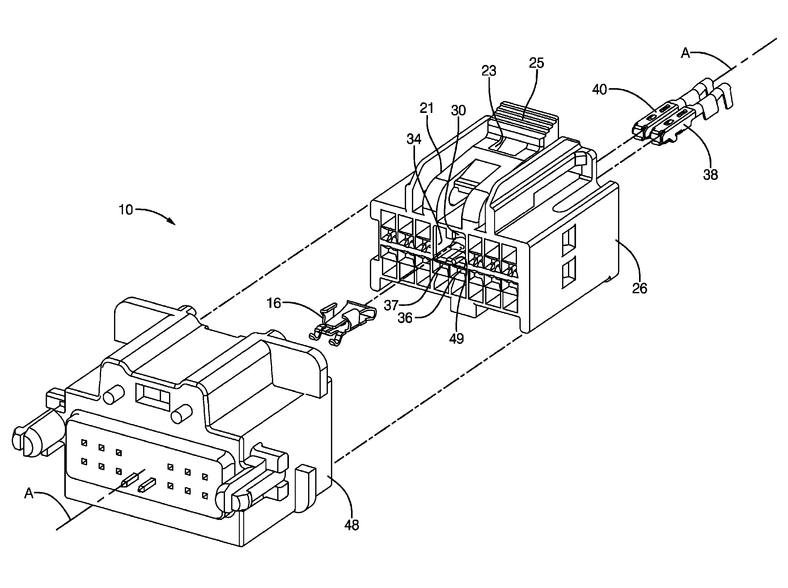
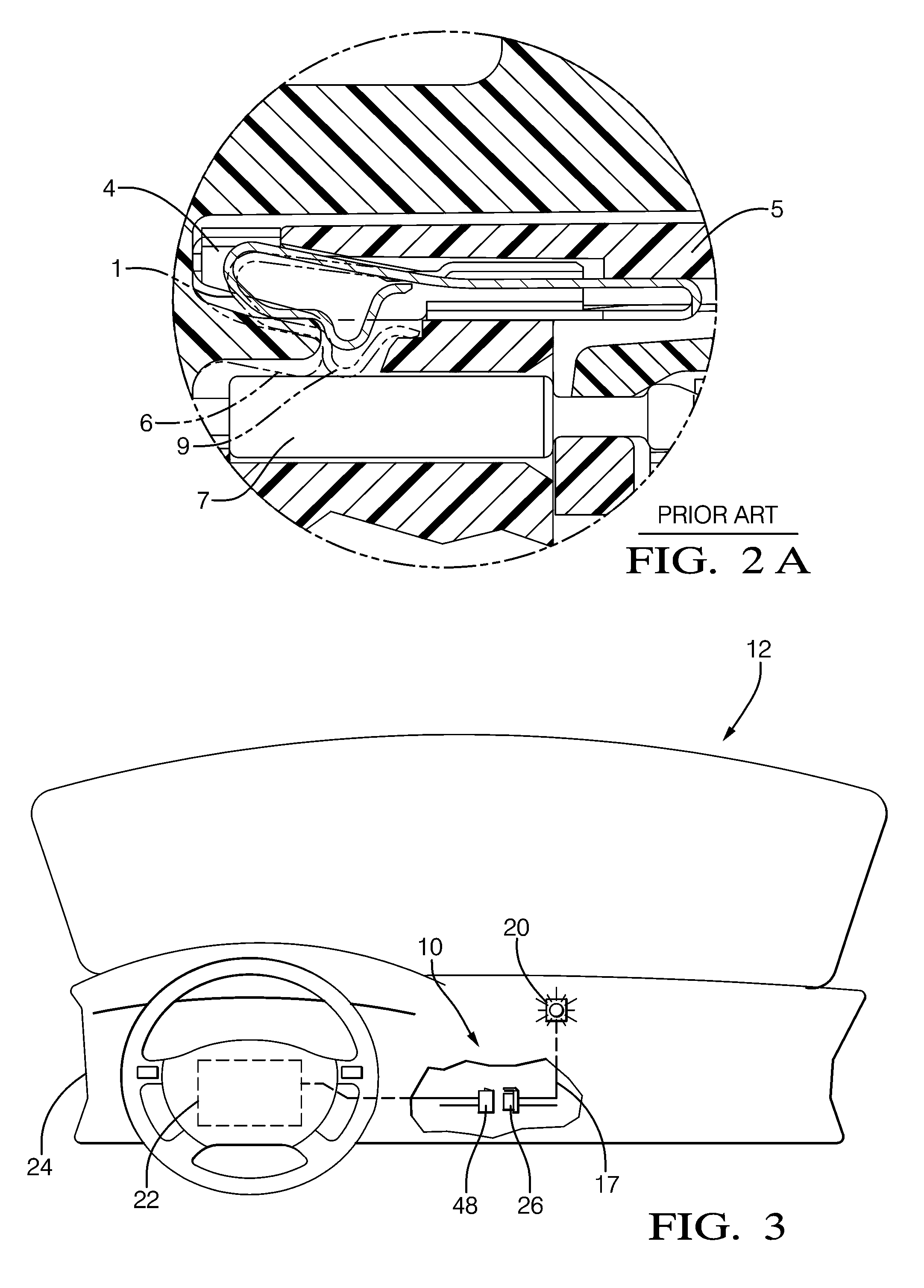
[0026]Referring to FIGS. 3-4, a shorting clip terminal connector assembly 10 is provided in accordance with one aspect of the invention in an interior compartment 12 of a vehicle (not shown). Assembly 10 includes a shorting clip terminal 16 disposed within assembly 10. When the shorting clip terminal connector assembly is assembled, the shorting clip terminal operates in a first operation state that does not alter the normal operation of an electrical circuit affected by the shorting clip terminal. When connector bodies of assembly 10 are disconnected, as illustrated in FIG. 3, shorting clip terminal 16 is configured in a second operation state where the performance of an electrical circuit 17 is altered from the first operation state. An indicator light 20 for an air bag system 22 in the vehicle illuminates on an instrument panel 24 of the vehicle. Illumination of the air bag indicator light provides visual indication for a service technician that the air bag in the vehicle is inop...


PUM


Abstract

A shorting clip terminal connector assembly electrically shorts together terminals in a first connector body dependent on connection status of a first and a second connector body. A shorting clip terminal disposed in a shorting clip terminal cavity in the first connector body receives a protrusion disposed on the second connector body. When the second connector body is mated with the first connector body, the protrusion engages a lift element of the shorting clip terminal in the shorting clip terminal cavity thereon and urges the lift element to lift contact elements of the shorting clip terminal away from the terminals in the shorting clip terminal cavity enabling insertion of protrusion side walls intermediate the contact elements and the terminals in the shorting clip terminal cavity. The contact elements of the shorting clip terminal do not make electrical contact with the terminals and the protrusion side walls further shield the contact elements from making electrical contact with the terminals.

Description

TECHNICAL FIELD[0001]This invention is directed to a shorting clip terminal connector assembly. More particularly, a provision on a second connector body assures that a shorting clip terminal does not electrically short a first terminal with a second terminal in a first connector body when it should not.BACKGROUND OF INVENTION[0002]It is known to use a shorting clip terminal in an automotive vehicle to electrically short an electrical signal provided on a terminal with another electrical signal provided on another terminal to selectively affect the performance of an electrical circuit. Referring to FIG. 1, a common prior art shorting clip terminal (1) is illustrated. The shorting clip terminal (1) includes a front end (2) and a contact point (3). Referring to FIG. 2, the terminal (1) is mounted in a cavity (4) of the housing (5). A wall portion (6) of the housing (5) assists to hold the terminal (1) within the cavity (4) and separates the shorting clip terminal (1) from electrical c...

Claims


Application Information

Patent Timeline
IPC IPC(8): H01R29/00
CPCH01R13/7032
Inventor WICKS, JOHNMCCALL, MARK D.LIPTAK, NICOLE L.LAM, PAUL S.
Owner APTIV TECH LTD
Why Eureka
Try Eureka