
Managing electrical device power state

a technology for managing electrical devices and power states, applied in power management, high-level techniques, instruments, etc., can solve problems such as device undesired power consumption, device damage, device may undesired power consumption,

Inactive Publication Date: 2011-06-07
INT BUSINESS MASCH CORP
View PDF9 Cites 1 Cited by
  • Summary
  • Abstract
  • Description
  • Claims
  • Application Information

AI Technical Summary

Benefits of technology

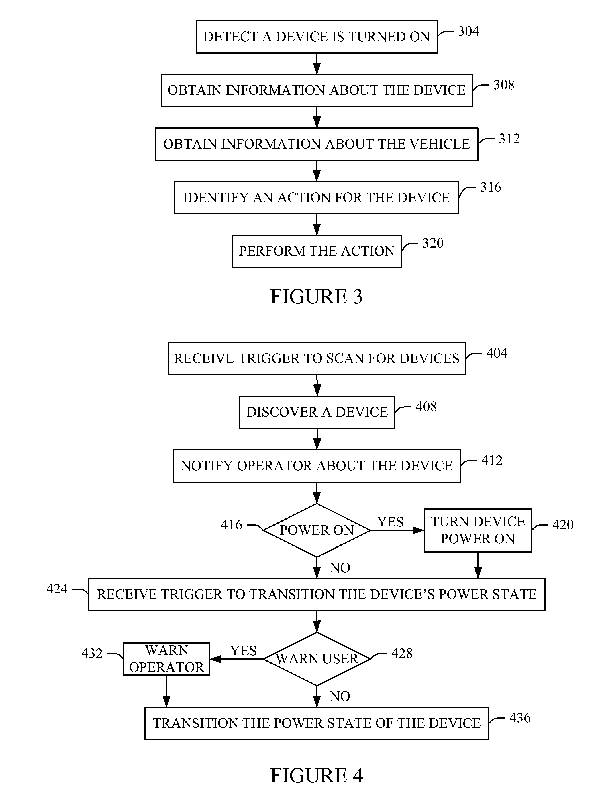
The patent describes an automobile control system that can manage the power state of a portable electrical device in a region around a vehicle. The system can detect the presence of the device and obtain information about it, such as its power state. The system can then identify an action to be taken based on the information, such as turning the device on or off. The system can also generate a signal to the operator of the vehicle to indicate the action to be taken. The patent also describes a method for deploying an application to facilitate fueling a vehicle by identifying the power state of the portable electrical device and generating a signal to transition it to a new power state based on the user's desired power state. The technical effects of the patent include improved management of portable electrical devices in a vehicle and improved user experience for fueling a vehicle.

Problems solved by technology

If such a device is turned on and left in the automobile when all of the occupants of the automobile have exited the automobile, the device may undesirably consume power from the battery supplying power to the device and / or may become damaged due to the environment.
By way of example, such a device may undesirably consume power from one or more batteries installed in the device or from the vehicle's battery when the device is receiving power from the vehicle's battery.
In another example, the temperature of the device may fall outside of the operating temperature range for the device, which may cause damage to one or more component of the device, as the temperature in the automobile changes.

Method used


Image

  • Managing electrical device power state
  • Managing electrical device power state
  • Managing electrical device power state

Examples


Embodiment Construction

[0017]For convenience purposes, the Detailed Description of the Invention has the following sections

[0018]I. General Description

[0019]II. Computerized Implementation

I. General Description

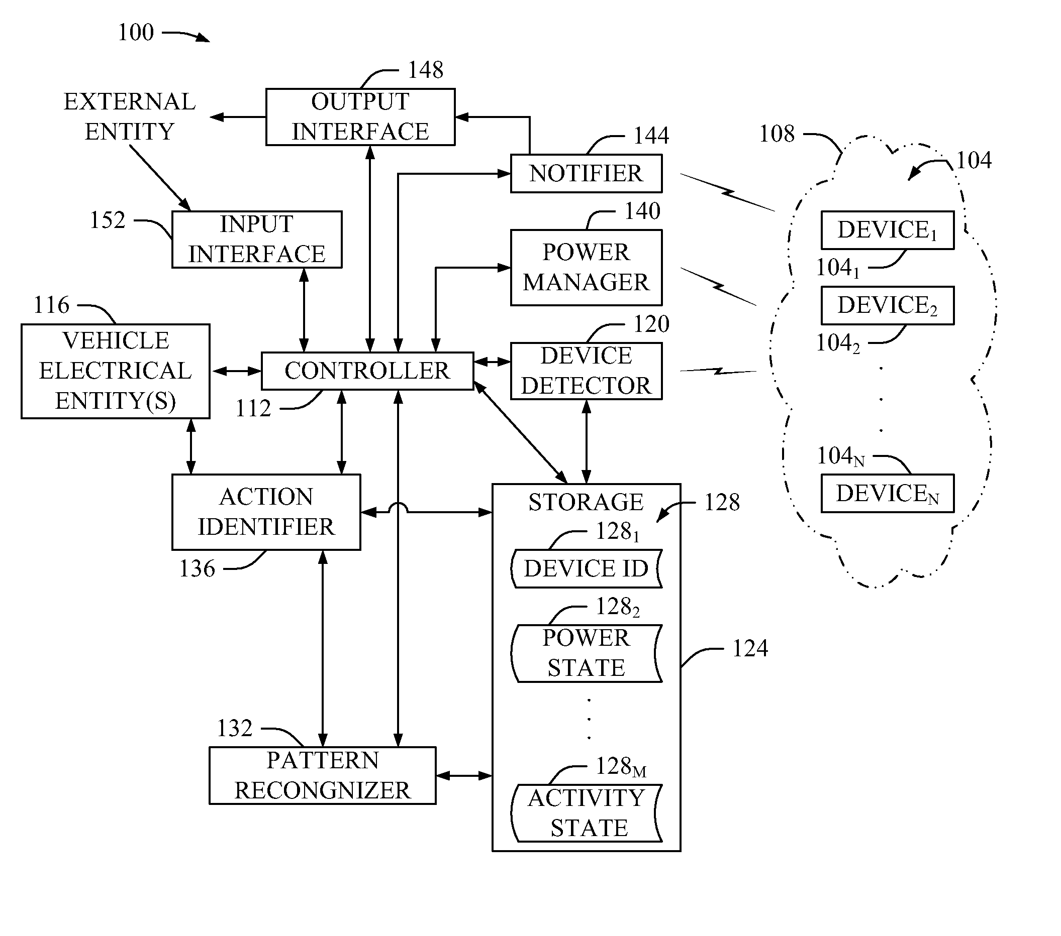
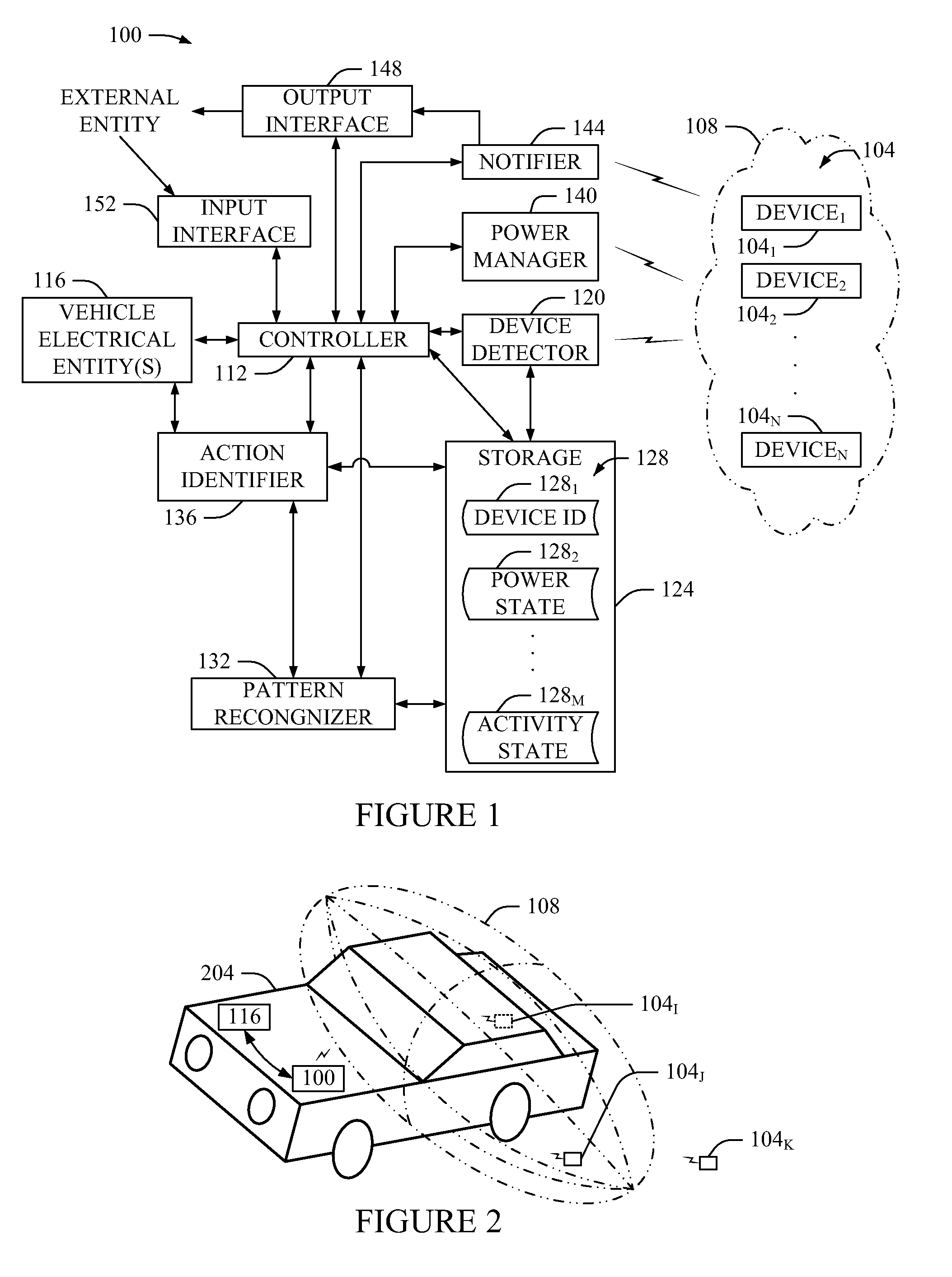
[0020]FIG. 1 illustrates a non-limiting example of a vehicle control system 100 that facilitates managing the power state of one or more portable electric devices 104 located within a region 108 monitored by the system 100. In one instance, the region 108 encompasses the entire vehicle. In another instance, the region 108 encompasses a sub-portion of the vehicle. Optionally, the region 108 additionally or alternatively encompasses a region outside of the vehicle. It is also noted that the particular shape of the illustrated region 108 is shown for explanatory purposes and is not limiting. As such, the region 108 may be otherwise shaped, including in two or three dimensional configurations. In addition, one or more other regions may be concurrently or alternately monitored by the system 100.

[0021]In ...


PUM


Abstract

A system, method, and program product that manages the power state of a portable electrical device located within a monitored region about a vehicle. Information about the portable electrical device such as the power state of the portable electrical device is obtained and used to identify an action for the portable electrical device. Suitable actions include, but are not limited to, transitioning the power state of the portable electrical device and / or providing a notification about the portable electrical device. Other information such as the state of the ignition of the vehicle and / or the proximity of the driver and / or a passenger(s) with respect to the vehicle may additionally or alternatively be used to determine the action.

Description

FIELD OF THE INVENTION[0001]The present invention generally relates to automobiles and, more particularly, to a method, system, and program product of an automobile that manages the power state of a portable electrical device.BACKGROUND OF THE INVENTION[0002]An automobile occupant such as a driver or a passenger may have a portable electrical device such as an electrically-powered game, a cell phone, a CD player, a DVD player, etc. in his / her possession when the occupant is in the automobile. Such a device can be turned on while the automobile is running and / or while the automobile is turned off.[0003]If such a device is turned on and left in the automobile when all of the occupants of the automobile have exited the automobile, the device may undesirably consume power from the battery supplying power to the device and / or may become damaged due to the environment.[0004]By way of example, such a device may undesirably consume power from one or more batteries installed in the device or...

Claims


Application Information

Patent Timeline
Patent Type & Authority Patents(United States)
IPC IPC(8): G08B13/14
CPCH04L12/10H04L12/12H04M1/6075H04W52/0274H04L67/125H04M1/6091H04M1/7253H04M1/72563H04W52/027Y02B60/50Y02D30/70H04M1/72412H04M1/72448
Inventor BOSS, GREGORY J.FINN, PETER G.HAMILTON, II, RICK A.O'CONNELL, BRIAN M.SEAMAN, JAMES W.WALKER, KEITH R.
Owner INT BUSINESS MASCH CORP
Learn More