Data transmission system for wireless communication

a wireless communication and data transmission technology, applied in the field of data transmission systems, can solve the problems of difficult modification of existing wiring, difficult wiring of the units involved, and difficulty in wiring the units involved,

Inactive Publication Date: 2011-06-14
VEGA GRIESHABER GMBH & CO
View PDF16 Cites 3 Cited by
  • Summary
  • Abstract
  • Description
  • Claims
  • Application Information

AI Technical Summary

Benefits of technology

[0013]According to another exemplary embodiment of the present invention, a simple data transmission system for wireless communication may be provided.
[0054]A field bus conversion device may allow protocol specific commands to be converted into field bus signals. This conversion may take place according to a field bus protocol. The field bus protocol or the field bus conversion device may have a timer, which may serve to monitor the expiry of a certain waiting period. This may be e.g. a register, which may be decremented in a corresponding time unit. By a timeout adaptation device, this timeout or timing behavior may be adapted to modified circumstances. E.g. it may thus be possible to take into account a timing behavior, which may have changed in relation to a standard due to the introduction of radio signal transmission. E.g. longer signal propagation times may be taken into account.

Problems solved by technology

Herein, wiring of the units involved may turn out to be difficult, e.g. when obstacles, such as the course of a river or the like, have to be passed.
Also, existing wiring is rather difficult to modify, and a required extension can be problematic.
For complex geographical structures or widely separated measuring units wiring can eventually be complicated and expensive.
Furthermore, wiring is not very flexible in case of modifications.
Circuitry required for wired communication is complicated and expensive and furthermore not flexible.
Although conditions regarding transmitting power and interference with adjacent frequency ranges have to be met, within the free ISM band, transmission interferences of the many units operating in this band may occur.
Such interferences may possibly require transmitted information to be repeated.
Thus, delays can occur at the time of transmission.

Method used


Image

  • Data transmission system for wireless communication
  • Data transmission system for wireless communication
  • Data transmission system for wireless communication

Examples


Embodiment Construction

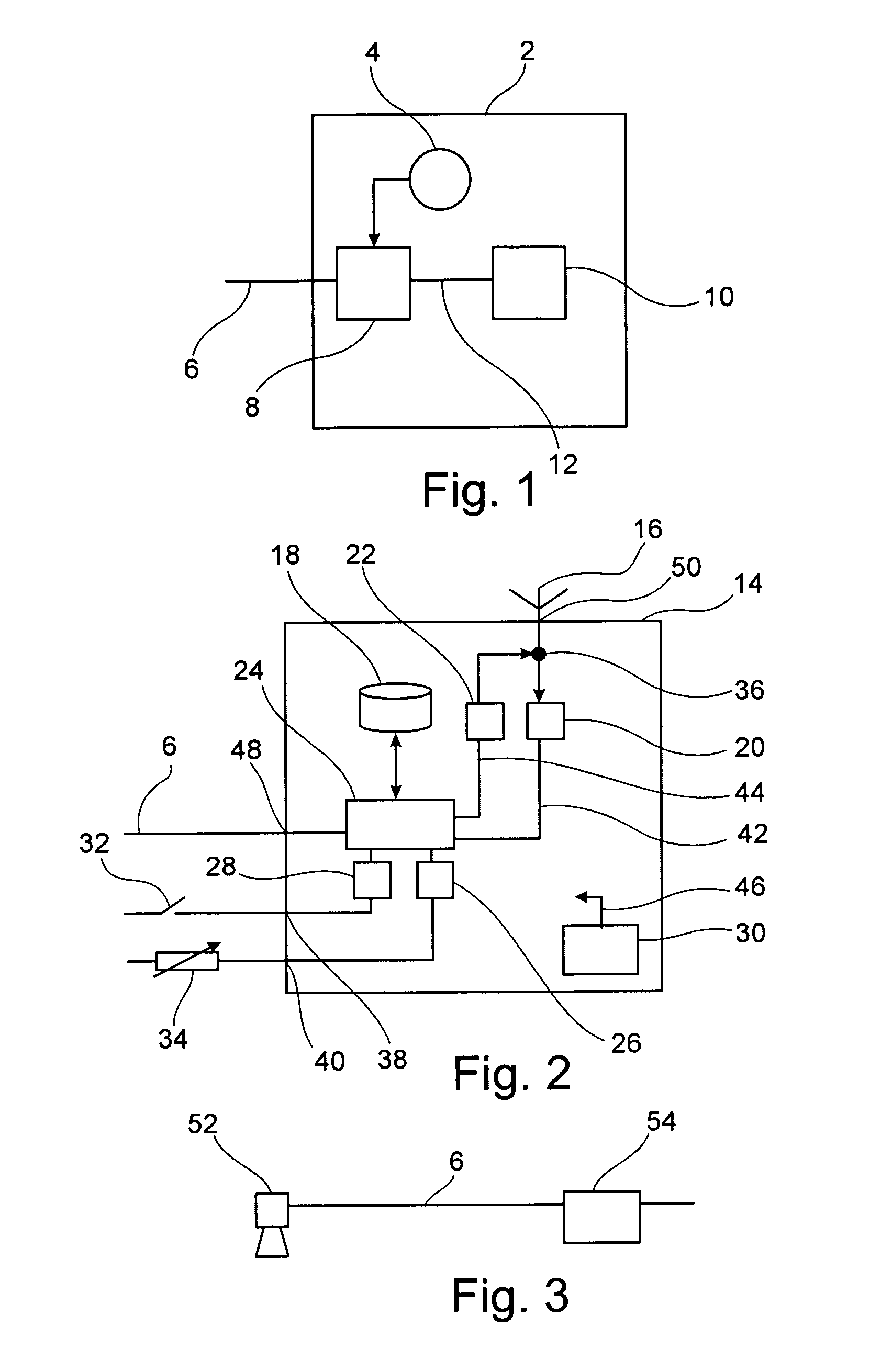
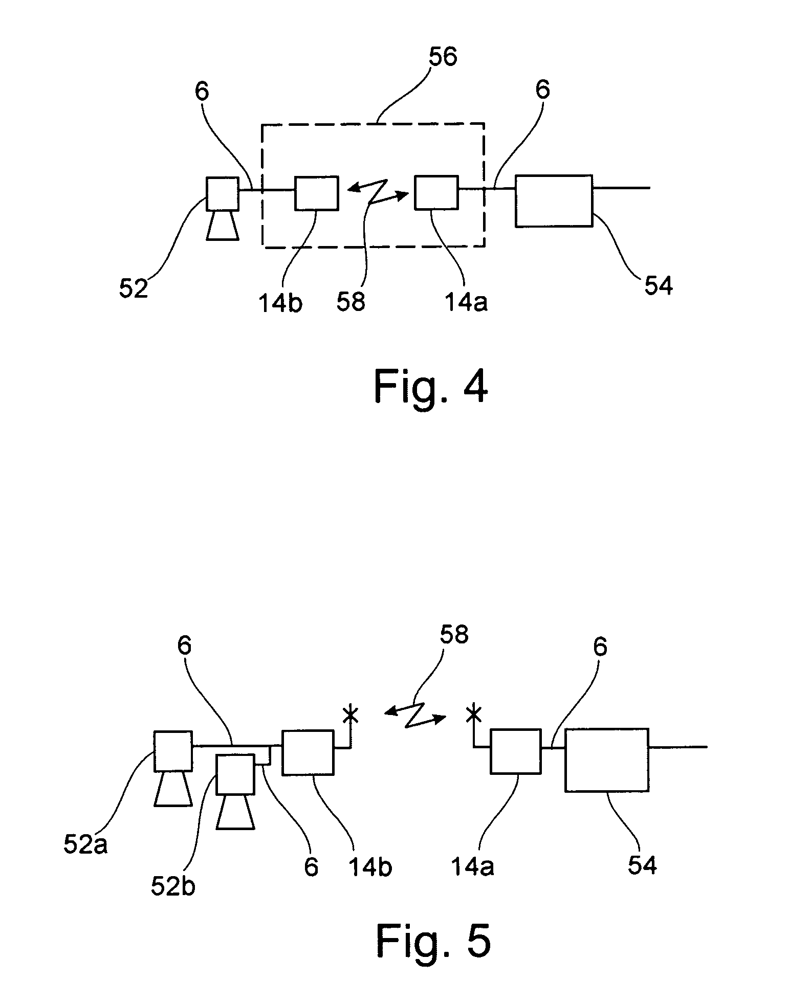
[0076]The illustrations in the figures are schematic and not to scale. In the following description of FIG. 1 to FIG. 9 the same reference numerals are used for identical or corresponding items.

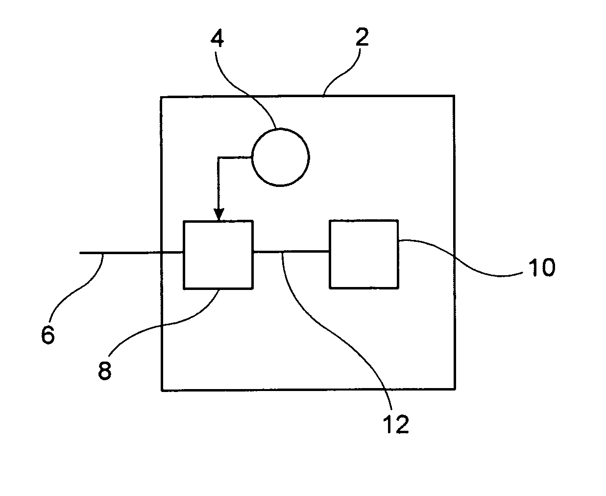
[0077]FIG. 1 shows a schematic block diagram of a control device according to an exemplary embodiment of the present invention. The control device 2 illustrated in FIG. 1 comprises a field bus conversion device 8 and a timeout adaptation device 4. The control device 2 further comprises the control signal device 10 and the field bus 6 or the field bus interface 6. The control signal device 10 can for instance be connected to an input device, whereby the control device 2 receives commands for detecting measured values.

[0078]In the control signal device 10, the input signals or commands, for instance provided via a man-machine interface, are converted into field bus specific commands. These commands correspond to the HART® protocol.

[0079]The control signal device 10 is connected to the field bus...


PUM


Abstract

This invention relates to a data transmission system for wireless communication of a control device with a field unit via a radio transmission device. The communication between control device and radio transmission device takes place via a field bus protocol. Likewise, the communication of the field unit with the radio transmission device takes place via a field bus protocol. The radio transmission device is capable of transmitting the field bus protocol by a radio protocol.

Description

PRIORITY CLAIM[0001]This application claims the benefit of the filing date of German Patent Application No. 10 2005 008 488.5-31 filed Feb. 24, 2005 and of U.S. Provisional Patent Application No. 60 / 656,463 filed Feb. 24, 2005, the disclosure of which is hereby incorporated herein by reference.FIELD OF THE INVENTION[0002]This invention relates to a data transmission system. In particular, this invention relates to a data transmission system for wireless communication, a control device for wireless communication with a field unit, a transmitting-receiving device and a method for wireless communication in a data transmission system.BACKGROUND[0003]A bus system shares a common medium for connecting several units to each other. As all units are linked to one bus, communication of each terminal with each other one can be enabled at one bus system, without each unit having to be connected to each other individually. E.g. to be able to connect each one of N terminals to each other, with a ...

Claims


Application Information

Patent Timeline
Patent Type & Authority Patents(United States)
IPC IPC(8): H04B17/00
CPCG05B19/042G08C19/02G08C17/02G05B2219/25186G05B2219/25428G05B2219/25196
Inventor ISENMANN, ANDREASFAIST, FRIDOLINSCHAETZLE, RALF
Owner VEGA GRIESHABER GMBH & CO
Why Eureka
Try Eureka