
Micro surgical cutting instruments

a cutting instrument and micro-scissor technology, applied in the direction of cuttinglery, manufacturing tools, incision instruments, etc., can solve the problem of increasing the risk of blade breaking, and achieve the effect of small cutting for

Inactive Publication Date: 2011-06-21
MYNOSYS CELLULAR DEVICES INC
View PDF63 Cites 10 Cited by
  • Summary
  • Abstract
  • Description
  • Claims
  • Application Information

AI Technical Summary

Benefits of technology

[0007]The devices and method described herein teach micro-machined blades, knives and cutting instruments. Such micro-machined devices are atomically sharp as described below. Such a construction provides precise cutting of tissue while minimizing collateral damage to tissues.
[0012]This reinforced shell configuration permits fabrication of micro-knives having radii of curvature between 5-50 angstroms. As noted above, such radii are significantly less than conventional micro-blades. However, as noted above, variations of the invention include knives with radii of curvature up to 500 angstrom. The reinforcement provided by the rigid filler material prevents the blade surface from deflecting and / or bending that would otherwise crack the blade surface. In most variations of the device, the smoothness of the blade allows the blade to actually contact the object to be cut. There are no gaps or aberrations in roughness where a cell may be missed by the cutting edge. The small radius of curvature of the cutting edge allows for a small cutting force. It follows that cutting of cells occurs without tearing or otherwise damaging the cells. It is also noted that knives fabricated by the disclosed process will have a cutting edge (or outer shell cutting edge) having a radius of curvature that is less than or equal to a radius of curvature of an adjacent edge of the body portion. This construction is possible mainly due to the fact that the cutting edge or outer edge is deposited first. Then the body portion is deposited within the cutting edge.

Problems solved by technology

Exceeding a depth of cut more than about 20 times the width of the blade of the micro-knife may increase the risk of breaking the blade.

Method used


Image

  • Micro surgical cutting instruments
  • Micro surgical cutting instruments
  • Micro surgical cutting instruments

Examples


Embodiment Construction

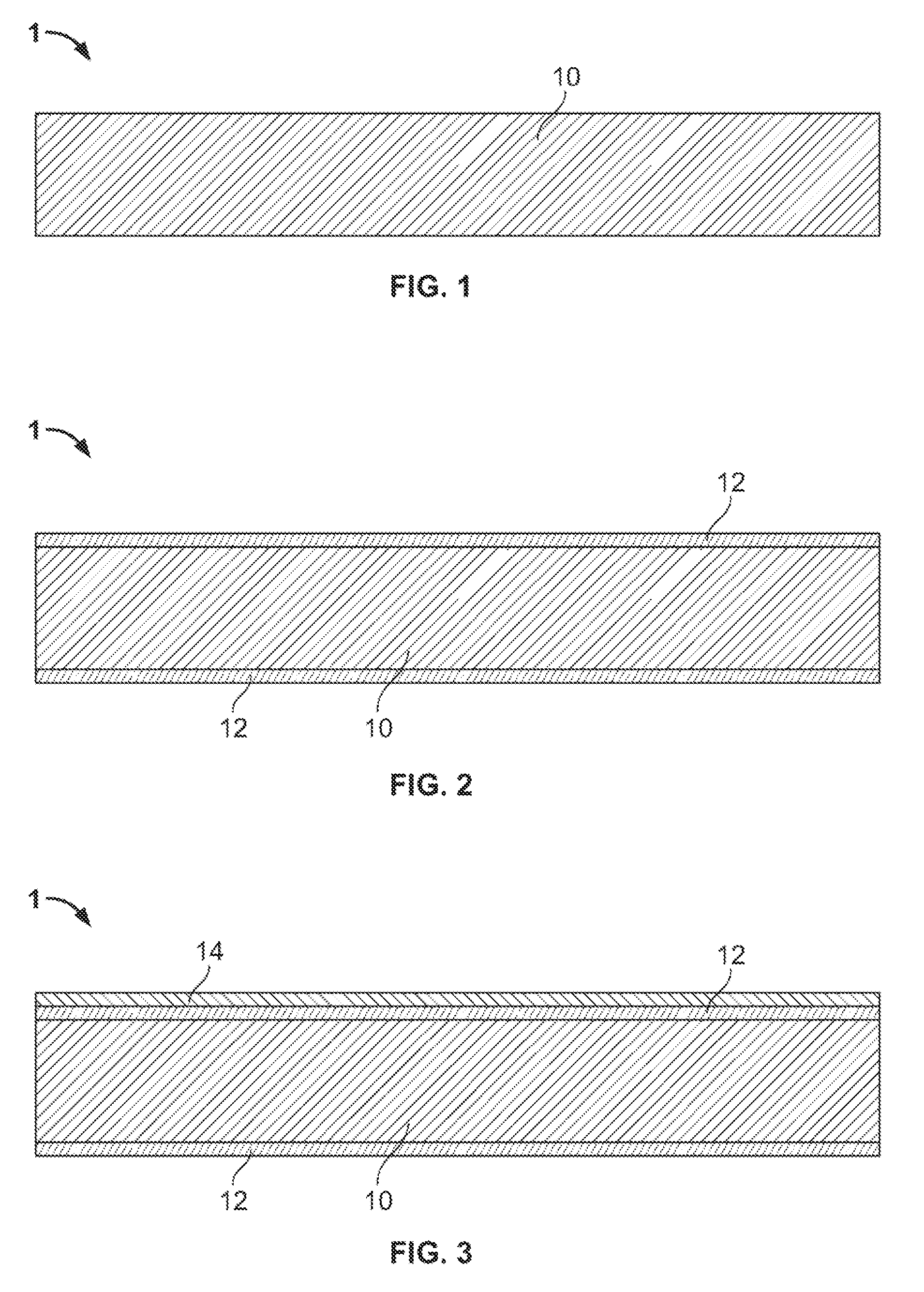
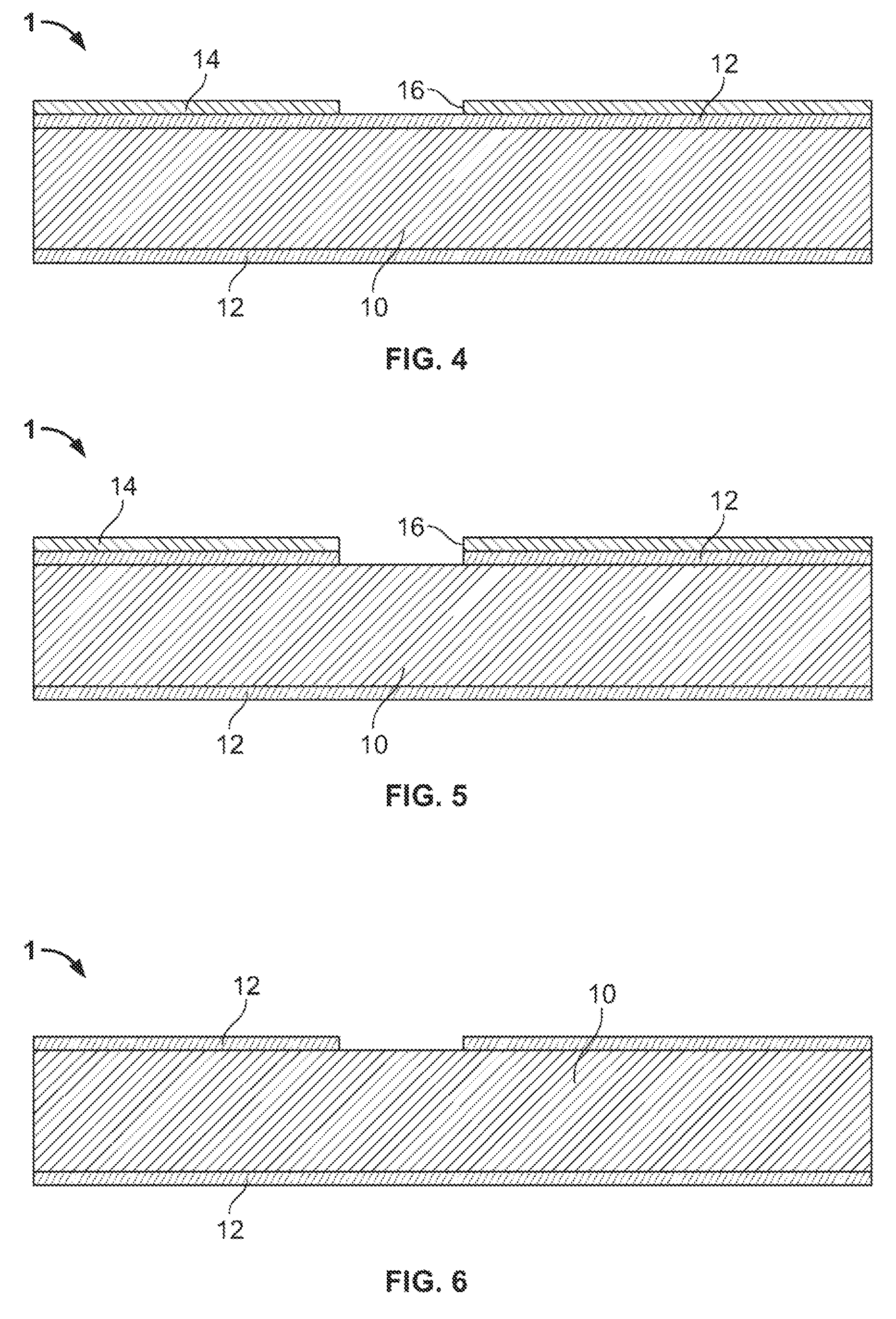
[0025]FIGS. 1 to 18 and the accompanying text illustrate one possible method of manufacturing a micro machined device according to a variation of the present invention. It will be appreciated that variations of the following example are within the scope of the invention.

[0026]FIG. 1 shows the start of a wafer assembly 1 as being a cross section of a (100) single crystal silicon wafer 10 that will be used to form the mold for the knife.

[0027]FIG. 2 shows a cross section of the wafer assembly 1 comprising the (100) single crystal silicon wafer with a layer of silicon dioxide 12 grown on it. Typically the silicon dioxide layer 12 is about 1 micron thick, and is grown at 1100 degrees C. in oxygen with steam present.

[0028]FIG. 3 shows the addition of a layer of photoresist 14 applied over the silicon dioxide layer 12. The photoresist 14 may be applied in a number of ways (e.g., spin applied over the oxide layer.)

[0029]FIG. 4 illustrates the photoresist once patterned to reveal exposed ar...


PUM

PropertyMeasurementUnit
thickaaaaaaaaaa
lengthaaaaaaaaaa
forceaaaaaaaaaa

Abstract

The present invention relates to methods and apparatus for micro surgical blades, knives and assemblies.

Description

[0001]This application is a continuation of International Application No. PCT / US2006 / 061459 filed Dec. 1, 2006 which is a non-provisional of U.S. Provisional Application No. 60 / 741,200 entitled Micro Surgical Cutting Instruments, filed on Dec. 1, 2005, the entirety of which are incorporated by reference herein.FIELD OF THE INVENTION[0002]The present invention relates to methods and apparatus for micro surgical blades, knives and assemblies.BACKGROUND OF THE INVENTION[0003]Conventional metal, diamond tipped or other similar type knives have blade edges or cutting surfaces that are considerably large when viewed on an atomic scale. Typically such knives have cutting edges ranging from 500 angstroms to about 1000 angstroms. Typically, such knives provide poor surgical precision and cause unnecessary destruction of tissue when viewed at the cellular level.[0004]Presently, atomic force microscopy uses devices having atomically sharp-tips for the manipulation and separation of cells. Such...

Claims


Application Information

Patent Timeline
Patent Type & Authority Patents(United States)
IPC IPC(8): B26B9/00B26B9/02
CPCA61B17/3211A61B17/205A61B2017/00526A61B2017/00345
Inventor KELLER, CHRISTOPHER GUILD
Owner MYNOSYS CELLULAR DEVICES INC
Learn More