
Electric toy gun and motion control mechanism thereof

a technology of motion control mechanism and electric toy gun, which is applied in the direction of compressed gas gun, white arms/cold weapons, weapons, etc., can solve the problems of inability to see the operation of various parts, inability to know the difference between the operation of parts, and limited use of conventional electric toy guns

Inactive Publication Date: 2011-06-21
YICK FUNG INDAL INT
View PDF12 Cites 12 Cited by
  • Summary
  • Abstract
  • Description
  • Claims
  • Application Information

AI Technical Summary

Benefits of technology

"The present invention is about an electric toy gun with a motion control mechanism that is similar to a real gun in terms of its operation and behavior. The electric toy gun has a repositioning set and air release holes, which make it more suitable for military training and last longer. The motion control mechanism includes a gear set, piston set, and primary and secondary repositioning springs. The repositioning set may have a repositioning rod and recoil mass. The repositioning rod may have bulges and a gliding slot set in the gun body. The repositioning set may have two pairs of bulges and two gliding slots that match the bulges. The motion control mechanism provides a positioning hole for fixing the repositioning rod and recoil mass together. The secondary repositioning spring may be fixed to the repositioning rod and inner front wall of the chamber. The electric toy gun is more suited for military training and can last longer."

Problems solved by technology

Since all parts in a conventional electric toy gun are hidden, users would not be able to see operation of various parts in the gun, and would not know the difference between the operation of the parts in a conventional electric toy gun and that of a real gun.
Nevertheless, due to the difference in the mechanism between conventional electric toy guns and real guns, in the context of military training conventional electric toy guns are of limited use.

Method used


Image

  • Electric toy gun and motion control mechanism thereof
  • Electric toy gun and motion control mechanism thereof
  • Electric toy gun and motion control mechanism thereof

Examples


Embodiment Construction

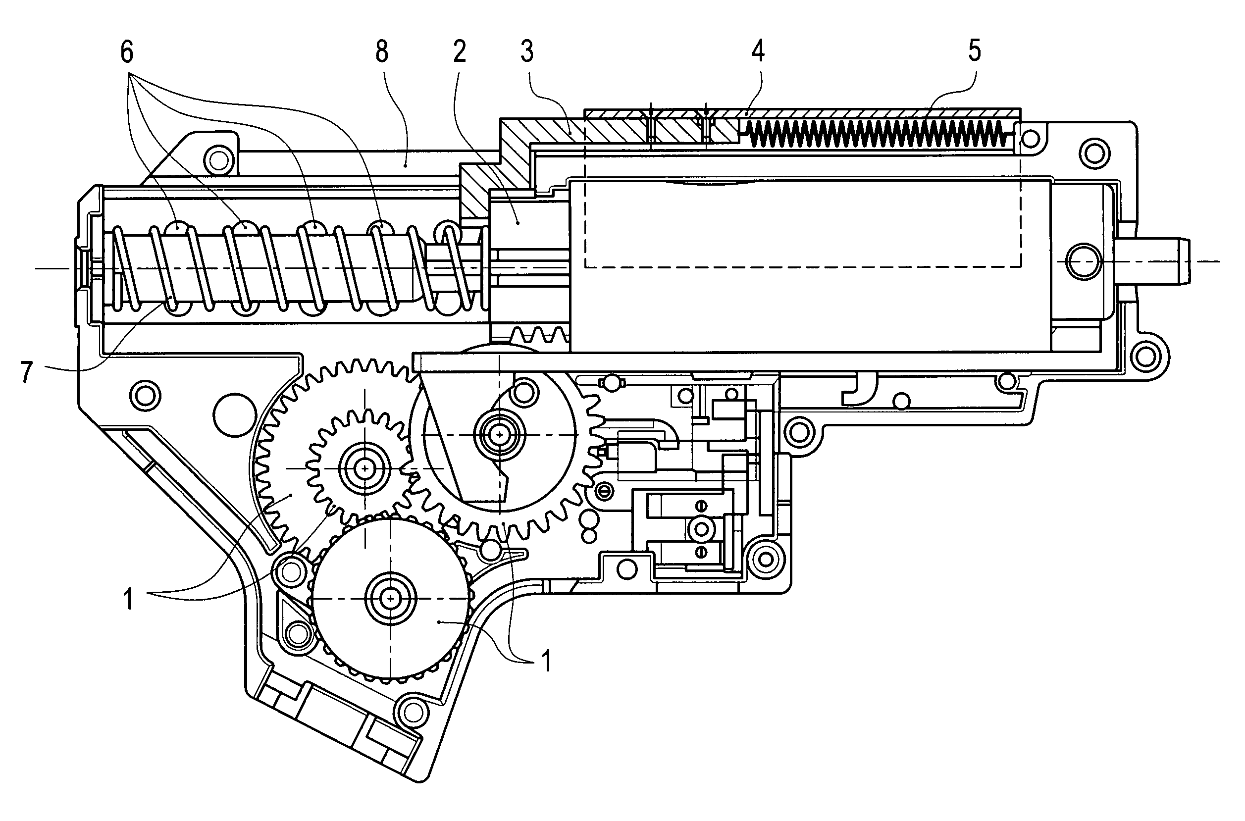
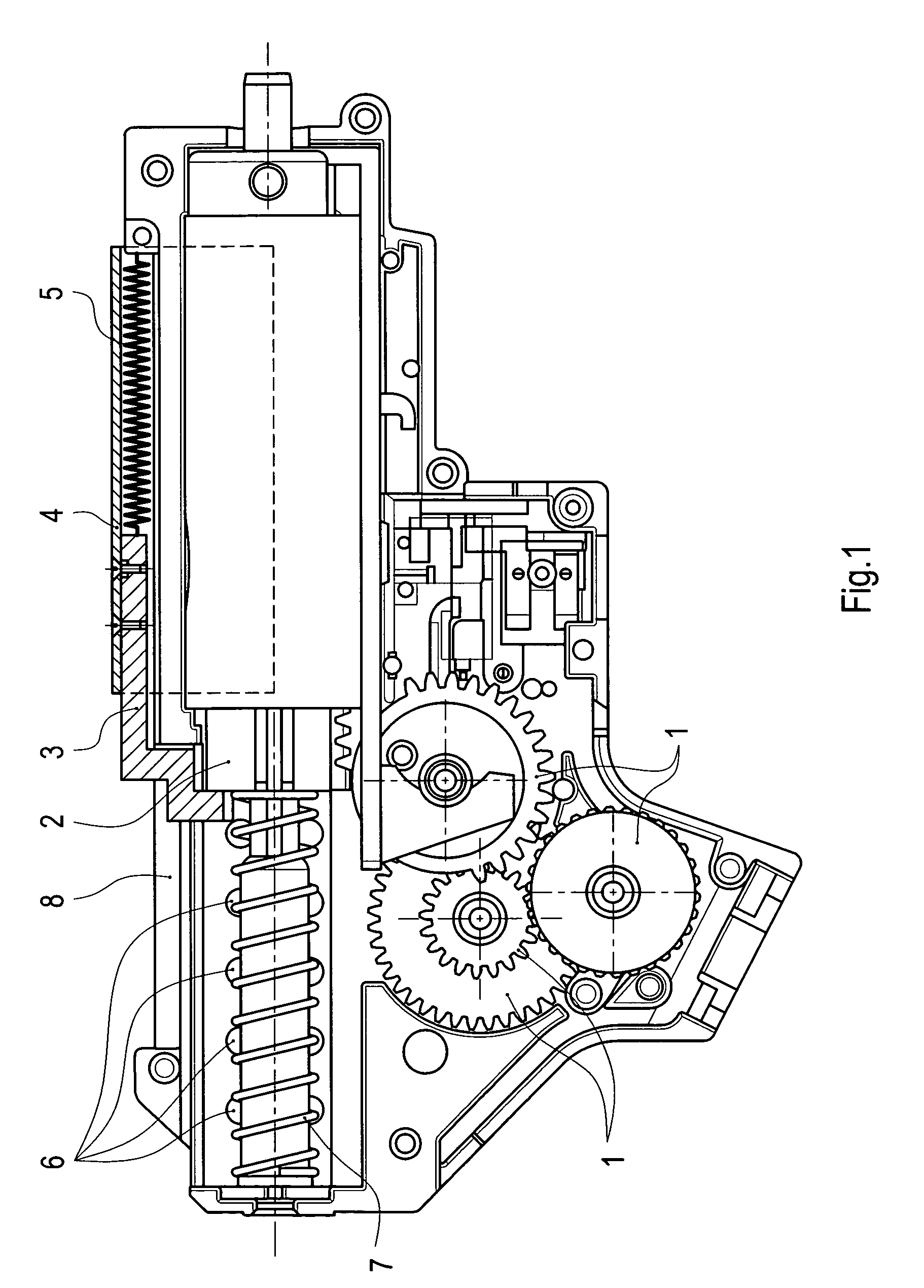
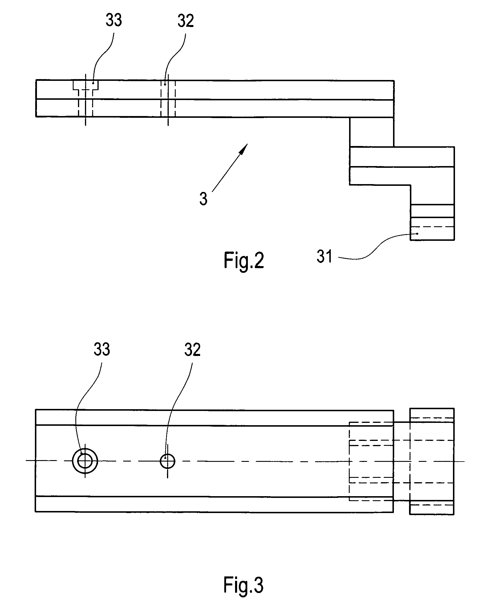
[0021]An embodiment of an electric toy gun in accordance with the present invention is illustrated in FIG. 1. The toy gun comprises a motion control mechanism having a gear set 1, a piston set 2, a repositioning rod 3, a recoil mass 4, a gliding set 8, a primary repositioning spring 7, a secondary repositioning spring 5, and an air release hole 6. The repositioning rod 3, the recoil mass 4, and the repositioning spring 5 are fixed together to form a repositioning set. The repositioning set is installed on the upper part of the chamber of the electric toy gun, while the recoil mass 4 is positioned externally to the chamber, and the recoil mass can be seen from the exterior of the electric gun. The gliding set 8 is in the upper rear part of the chamber, and two sets of gliding slots are provided on the gliding set 8. The repositioning rod 3 is provided with two pairs of bulges which correspondingly fit into the gliding slots. The gear set 1 and the piston set 2 are placed inside the c...


PUM


Abstract

This invention is a motion control mechanism for use in electric toy guns. The mechanism includes a gear set, a piston set that is inside the electric toy gun's body and driven by the said gear set, a primary repositioning spring that is between the said piston set and the toy gun's rear end, and the repositioning set that is installed on the gun body, and moves backward when driven by the said piston set. The said repositioning set is fixed to the piston set, and will move backward when driven by the gear set. It will then reposition itself by the force of primary repositioning spring. The electric toy guns with this invention have the following advantageous features: Since it has a repositioning set, and air release holes, it provides for motions that are more similar to those of real guns. Thus it is more suited for military training and lasts longer.

Description

TECHNICAL FIELD OF THE INVENTION[0001]The present invention is concerned with an electric toy gun and in particular a motion control mechanism for use in an electric toy gun.BACKGROUND OF THE INVENTION[0002]In recent years, electric toy guns have become very popular and they are widely used in outdoor war games and in military training. Electric toy guns and real guns have similar appearance. The general mechanism of conventional electric toy guns is that when they are triggered, a battery-powered gear set therein will backwardly drive a piston set in a gun chamber thereof. When the piston set is driven backwardly, a spring between a rear wall of the chamber and the piston set is compressed. When the gear set rotates to a predetermined position, the piston set is released. The spring will then push the piston set forward such that pressurized air in the chamber will drive a BB bullet to be ejected from a barrel of the gun. It can thus be understood that after a shot is fired, the gu...

Claims


Application Information

Patent Timeline
Patent Type & Authority Patents(United States)
IPC IPC(8): F41B11/00F41B11/64F41B11/646F41B11/68F41B11/71
CPCF41B11/646
Inventor PONG, JACKIE CHUN CHUNG
Owner YICK FUNG INDAL INT
Learn More