Stacked package module and board having exposed ends

a technology of package modules and ends, applied in the direction of printed circuit aspects, electrical apparatus construction details, association of printed circuit non-printed electric components, etc., can solve the problems of reduced elasticity of circuit layout on the substrate, design flexibility of package structures, and non-detachable electrical connections, etc., to achieve more elastic conductive pad layout, compact size and space-saving products

Active Publication Date: 2011-06-28
UNIMICRON TECH CORP
View PDF22 Cites 32 Cited by
  • Summary
  • Abstract
  • Description
  • Claims
  • Application Information

AI Technical Summary

Benefits of technology

[0011]The object of the present invention is to provide a stacked package module where a package structure with a chip embedded therein functions as a package unit, which can provide a more compact size and space-saving product. In addition, the ball grid array area of the package structure with a chip embedded therein is not limited by the chip area so as to provide a more elastic conductive pad layout, and the exposed electro-connecting ends of the stacked package module can further provide detachable electrical connections for the stacked package module with an electronic device. Furthermore, the utilization of a package on package (POP) method can connect different package structures by solder balls and conductive pads to provide a package module having the function of system integration for various products. The package structure with a chip embedded therein can further electrically connect to at least one passive component to meet the requirements for electrical characteristics.
[0016]Accordingly, the present invention provides a stacked package module wherein a package structure with a chip embedded therein functions as a package unit, which can provide a more compact size and space-saving product. In addition, the characteristics of the first circuit board electrically connecting to the first chip through the conductive vias can be employed in utilization of a chip with a more reduced pitch between electrode pads; since the circuit layout in the chip area of the first circuit board can be performed by the built-up structures, the ball grid array area of the package structure with a chip embedded therein is not limited by the chip area so as to provide a more elastic conductive pad layout. The exposed electro-connecting ends can further provide detachable electro-connections for the stacked package module with an electronic device. Furthermore, the utilization of the package on package (POP) method can connect different package structures to provide a package module having the function of system integration for various products, and the package structure with a chip embedded therein can further electrically connect to at least one passive component to make the product meet the requirements for electrical characteristics.

Problems solved by technology

However, in the above module comprising a plurality of stacked package structures, only the remaining region of the substrate of each package structure, where no semiconductor chip is disposed, can suffice conductive pads for electrically connecting with another package structure by solder balls.
It is indicated that the electrical connecting area on the substrate of each package structure is limited, and thereby the number and the layout of I / O connections of each package structure is limited, resulting in reduced elasticity of circuit layout on the substrate and design flexibility of the package structure.
In addition, soldering is the only method for electrically connecting the aforementioned package structure with an electronic device, resulting in nondetachable electrical connections.

Method used


Image

  • Stacked package module and board having exposed ends
  • Stacked package module and board having exposed ends
  • Stacked package module and board having exposed ends

Examples


embodiment 1

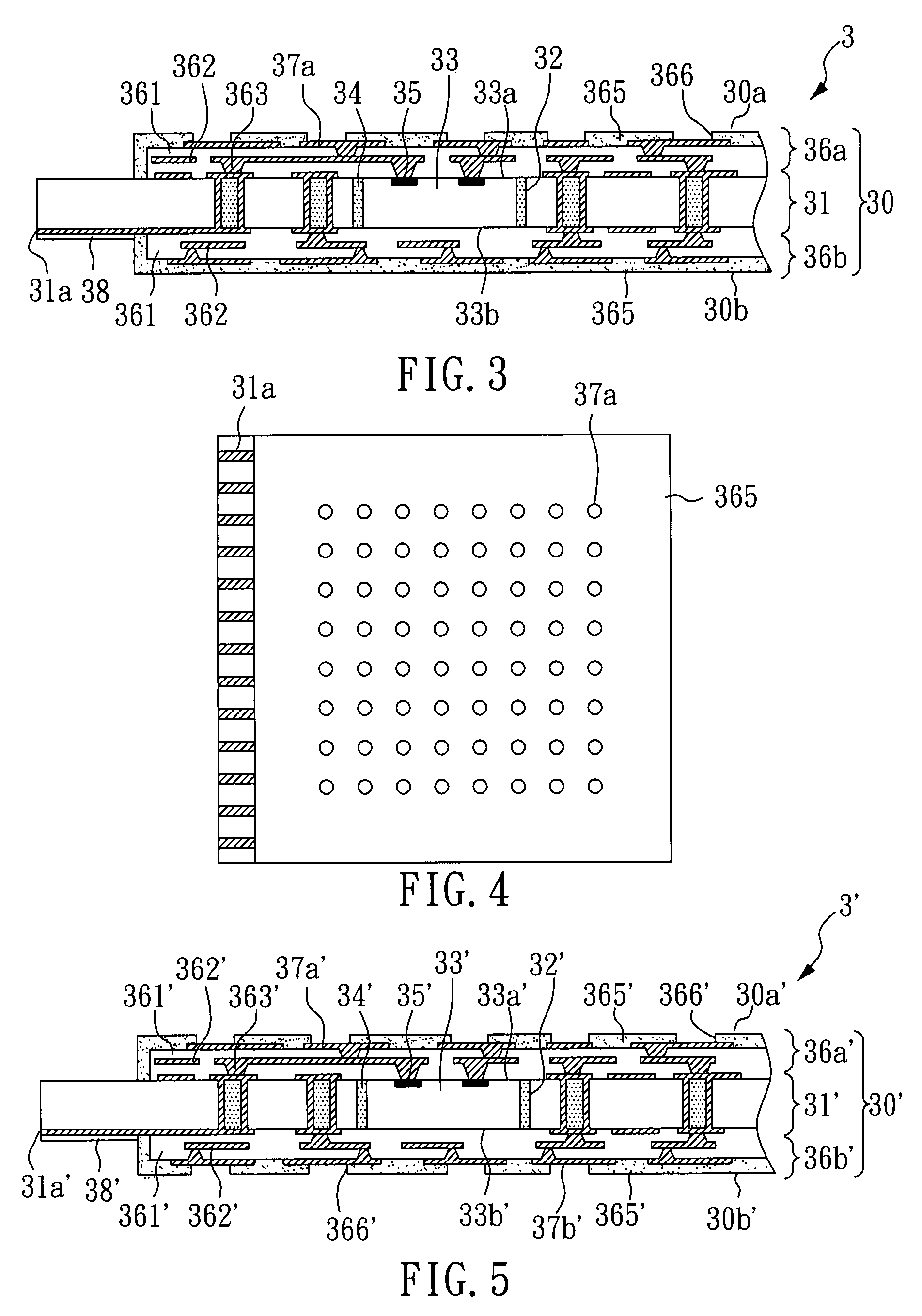
[0031]With reference to FIG. 3, there is shown a cross-section view of a package structure with a chip embedded therein. The package structure 3 with a chip embedded therein of the present embodiment comprises a first circuit board 30 with a first chip 33 embedded therein. The first circuit board 30 has a first surface 30a, an opposite second surface 30b, a plurality of exposed electro-connecting ends 31a, and a plurality of first conductive pads 37a on the first surface 30a. In detail, the first circuit board 30 has a core board 31 with a through cavity 32 therein, therewith the first chip 33 embedded in the cavity 32 of the core board 31, the gap between the core board 31 and the first chip 33 filled with a filling material 34 to fix the first chip 33, the first chip 33 having an active surface 33a and an opposite inactive surface 33b, wherein the active surface 33a has a plurality of electrode pads 35. The first circuit board 30 further comprises a first built-up structure 36a an...

embodiment 2

[0033]With reference to FIG. 5, there is shown a cross-section view of a package structure with a chip embedded therein. The package structure 3′ with a chip embedded therein of the present embodiment is the same as the package structure 3 of Embodiment 1, except that the package structure 3′ further comprises a plurality of second conductive pads 37b′, and the solder mask 365′ of the second built-up structure 36b′ has a plurality of openings 366′ to expose the second conductive pads 37b′.

embodiment 3

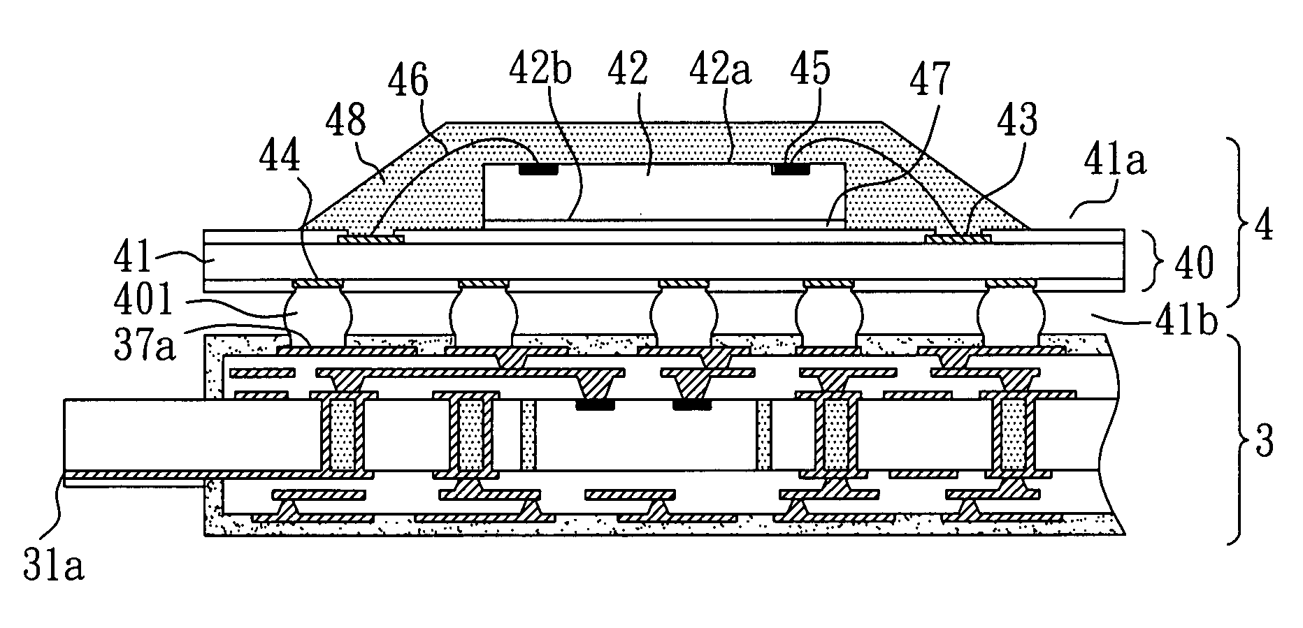
[0034]With reference to FIG. 6, there is shown a cross-section view of a stacked package module. The stacked package module of the present embodiment uses the package structure 3 of Embodiment 1 and a wire bonding package structure 4 as package units. The wire bonding package structure 4 comprises a second chip 42 and a second circuit board 40. In detail, the second circuit board 40 comprises: a substrate 41 having a first surface (for adhering a chip) 41a and an opposite second surface (for adhering solder balls) 41b; a plurality of wire bonding pads 43 disposed on the first surface 41a; and a plurality of second conductive pads 44 disposed on the second surface 41b. The second chip 42 has an active surface 42a having a plurality of electrode pads 45 thereon and an inactive surface 42b. The electrode pads 45 of the second chip 42 electrically connect to the wire bonding pads 43 on the first surface 41a of the substrate 41 through a plurality of metal wires 46. The inactive surface ...


PUM


Abstract

A stacked package module is disclosed, which comprises: a first package structure comprising a first circuit board with a first chip embedded therein, wherein the first chip has a plurality of electrode pads; the first circuit board comprises a first surface, an opposite second surface, a plurality of exposed electro-connecting ends, a plurality of first conductive pads on the first surface, a plurality of conductive vias, and at least one circuit layer, therewith the electrode pads of the first chip electrically connecting to the electro-connecting ends and the first conductive pads directly through the conductive vias and the circuit layer; and a second package structure electrically connecting to the first package structure through a plurality of first solder balls to make a package on package. The stacked package module of this invention has characters of compact size, high performance, high flexibility, and detachability.

Description

BACKGROUND OF THE INVENTION[0001]1. Field of the Invention[0002]The present invention relates to a stacked package module and, more particularly, to a stacked package module which can enhance the elasticity of conductive pad layout and the electro-connecting region.[0003]2. Description of Related Art[0004]In the development of electronics, the design trend of electronic devices is towards multifunction and high-performance. Thus, high-density integration and miniaturization are necessary for a semiconductor package structure. On the ground of reason aforementioned, the mono-layered circuit boards providing electrical connections among active components, passive components, and circuits, are being replaced by the multi-layered circuit boards. The area of circuit layout on the circuit board increases in a restricted space by interlayer connection to meet the requirement of high-density integrated circuits.[0005]In general, a conventional semiconductor package structure is made such th...

Claims


Application Information

Patent Timeline
Patent Type & Authority Patents(United States)
IPC IPC(8): H01L23/02H05K1/18H05K7/00H01L29/40H01L23/52H01L23/48
CPCH01L24/24H01L25/105H05K1/185H01L24/82H01L2224/73267H01L2224/24226H01L2224/24227H01L2224/48091H01L2224/73204H01L2924/01029H01L2924/01046H01L2924/01079H01L2924/14H01L2924/15153H01L2924/1517H01L2924/15311H01L2924/18165H01L2924/19105H05K1/023H05K1/117H05K3/4602H05K3/4694H05K2201/09845H05K2201/10734H05K2203/1572H01L2225/1058H01L2225/1035H01L2224/73265H01L2224/48227H01L2224/32225H01L2224/16225H01L2924/014H01L2924/01047H01L2924/00014H01L2924/00H01L2924/00012H01L24/73H01L2224/0554H01L2224/0557H01L2224/05571H01L2224/05573H01L2224/05599H01L2224/0555H01L2224/0556
Inventor WONG, LIN-YINYEH, MAO-HUATSAI, WANG-HSIANG
Owner UNIMICRON TECH CORP
Why Eureka
Try Eureka