Optimal drive frequency selection in electrical tomography

a technology of optical drive frequency and electrical tomography, applied in the field of electronic devices, can solve the problems of reducing the signal to noise ratio (snr), affecting the accuracy of the induced signal generated by the sensor electrode, and reducing the accuracy of the data derived

Inactive Publication Date: 2011-06-28
PROTEUS DIGITAL HEALTH INC
View PDF75 Cites 24 Cited by
  • Summary
  • Abstract
  • Description
  • Claims
  • Application Information

AI Technical Summary

Benefits of technology

[0005]The present invention may address at least one of the foregoing issues with provision of systems and methods of optimal drive frequency selection in electrical tomography. By using the aspects of the present invention, the drive frequency of the signal used to generate the electrical field of the ET system can be optimally selected. Multiple techniques can be used to quantify in-band noise. An analog or digital spectrum analyzer can be used to measure the power within a particular frequency band over a wide range of frequencies. Additionally, the receiver or demodulator of the signal processing module of the ET system can be used to select the drive frequency. This can be achieved by sweeping the carrier frequency of the demodulator over a wide range of frequency bands. The demodulated signal amplitude and standard deviation obtained through the two techniques can be used to select the drive frequency with the least noise present.

Problems solved by technology

Thus, the presence of noise or interferences in the bandwidth of the drive frequency may affect the accuracy of the induced signal generated by the sensor electrode.
Accordingly, the inherent noise or background signal may degrade the signal to noise ratio (SNR) and / or reduce the accuracy of the data derived from or otherwise associated with the induced signal.

Method used


Image

  • Optimal drive frequency selection in electrical tomography
  • Optimal drive frequency selection in electrical tomography
  • Optimal drive frequency selection in electrical tomography

Examples


Embodiment Construction

[0015]Reference will now be made in detail to the aspects of the invention, examples of which are illustrated in the accompanying drawings. While the invention will be described in conjunction with the aspects, it will be understood that they are not intended to limit the invention to these aspects. On the contrary, the disclosure is intended to cover alternatives, modifications and equivalents, which may be included within the spirit and scope of the invention. Furthermore, in the detailed description, numerous specific details are set forth in order to provide a thorough understanding of the present disclosure. However, it will be obvious to one of ordinary skill in the art that the present disclosure may be practiced without these specific details. In other instances, well known methods, procedures, components, and circuits have not been described in detail as not to unnecessarily obscure aspects of the present invention.

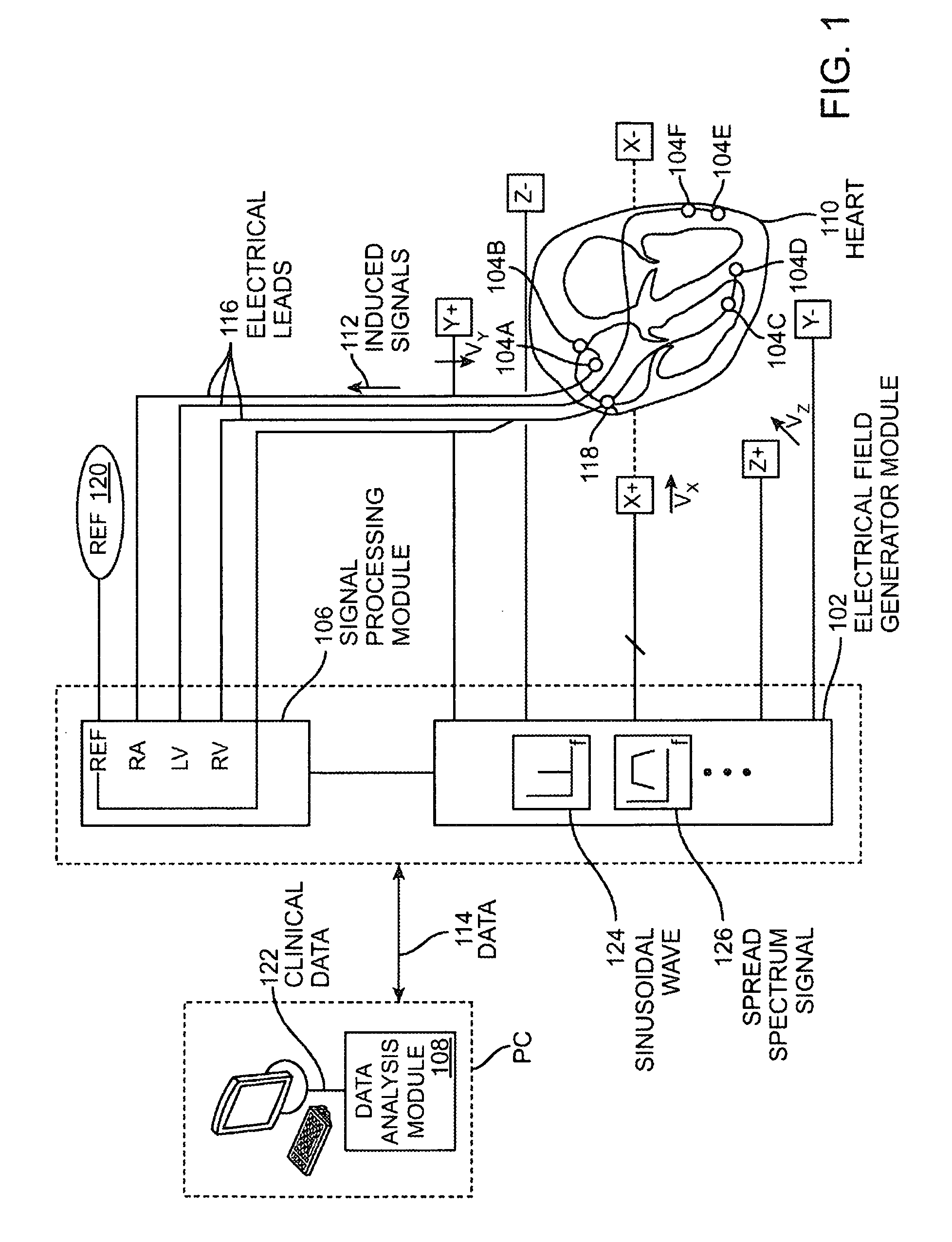
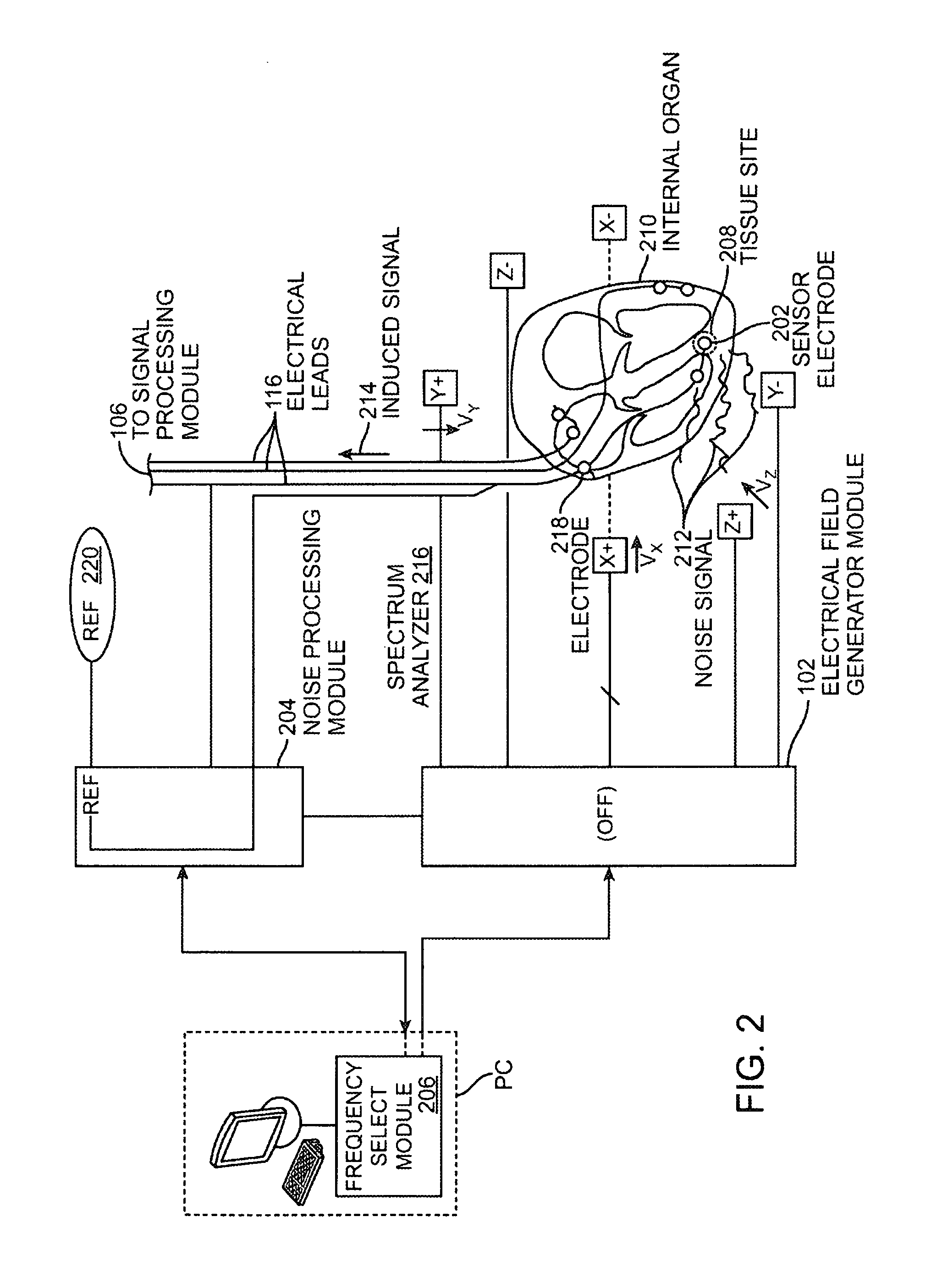
[0016]In continuous field tomography, a continuous field se...


PUM


Abstract

Electrical tomography drive frequency selection systems and methods are disclosed. One aspect of the present invention pertains to a system for optimally selecting a drive frequency of an electrical tomography which comprises a sensor electrode stably associated with a tissue site within an internal organ of a subject for generating an induced signal based on a noise signal over a range of frequency bands, wherein an electrical field for the electrical tomography is turned off. In addition, the system comprises a noise processing module for isolating the induced signal for each frequency band over the range of frequency bands. Furthermore, the system comprises a frequency select module for selecting a drive frequency of the electrical field for the electrical tomography by comparing the induced signal for each frequency band over the range of frequency bands.

Description

RELATED APPLICATION AND CROSS REFERENCE[0001]This application claims the benefit of U.S. Provisional Application Ser. No. 61 / 119,345 filed on Dec. 2, 2008, the entire disclosure of which is incorporated herein by reference.FIELD OF THE INVENTION[0002]Aspects of the present invention relate to the field of electronics. More particularly, aspects of the present invention relate to methods and systems of electrical tomography.INTRODUCTION[0003]Electrical tomography generally refers to imaging by sections or sectioning using an electrical field. In an electrical tomography system, an electrical field generator may generate the electrical field which is applied to a subject, e.g., a patient. In an electrical tomography (ET) system, a sensor electrode may be associated with a tissue site, e.g., an electrical lead having the sensor electrode physically associated with an organ. The sensor electrode then generates an induced signal in response to the electrical field applied to it. The indu...

Claims


Application Information

Patent Timeline
Patent Type & Authority Patents(United States)
IPC IPC(8): G01R29/26A61B5/05
CPCA61B5/05A61B5/415A61B5/7257
Inventor BEHZADI, YASHARCRANDALL, KENNETH C.
Owner PROTEUS DIGITAL HEALTH INC
Why Eureka
Try Eureka