Distributed rendering of texture data

a texture data and texture technology, applied in the field of graphics processing, can solve the problems of limiting the overall system performance, affecting the overall rendering performance, and the graphics application cannot inform the gpus of the spatial locality of the processed image data

Active Publication Date: 2011-06-28
NVIDIA CORP
View PDF6 Cites 58 Cited by
  • Summary
  • Abstract
  • Description
  • Claims
  • Application Information

AI Technical Summary

Benefits of technology

[0010]Yet another embodiment of the present invention provides a computing system for distributed rendering of texture data from a texture map. The computing system generally includes a central processing unit (CPU) subsystem for running a graphics application; a plurality of GPUs coupled to the CPU subsystem, wherein the graphics application utilizes an application programming interface (API) to control the plurality of GPUs such that each of the plurality of GPUs performs texture mapping on a texture map section from the texture map to render image data without replicating the rendered image data to the other GPUs in the plurality; and a means for combining the rendered image data to form a frame requested by the graphics application.

Problems solved by technology

However, as graphics applications begin to implement more steps with greater complexity in each step, the computational load on the GPU executing the processing steps increases, resulting in diminished overall rendering performance.
However, in current systems where multiple GPUs concurrently process a single frame, the graphics application has no way to inform the GPUs of the spatial locality of the processed image data.
All of the rendered data from each GPU has to be copied to all of the other GPUs to form a combined image, thereby limiting the overall system performance.

Method used


Image

  • Distributed rendering of texture data
  • Distributed rendering of texture data
  • Distributed rendering of texture data

Examples


Embodiment Construction

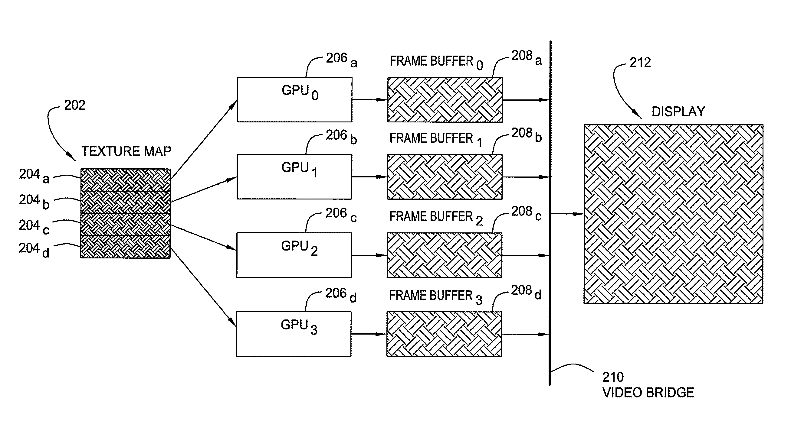
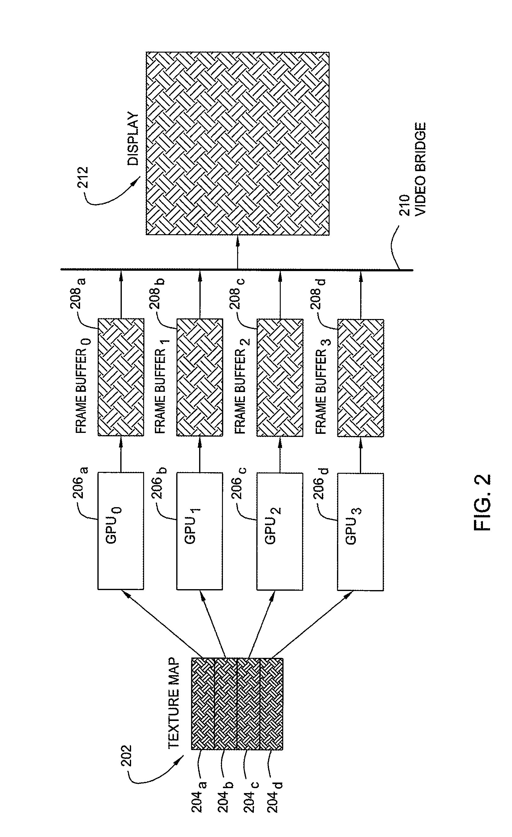
[0016]Embodiments of the present invention provide techniques (and corresponding apparatus) for distributing the workload of rendering an image where texture mapping is involved among multiple graphics processing units (GPUs). The techniques generally entail dividing a texture map among multiple GPUs, performing texture mapping in each GPU to render image data in each GPU's frame buffer, combining the image data from each frame buffer, and scanning out the combined image to a display.

An Exemplary Multi-GPU System

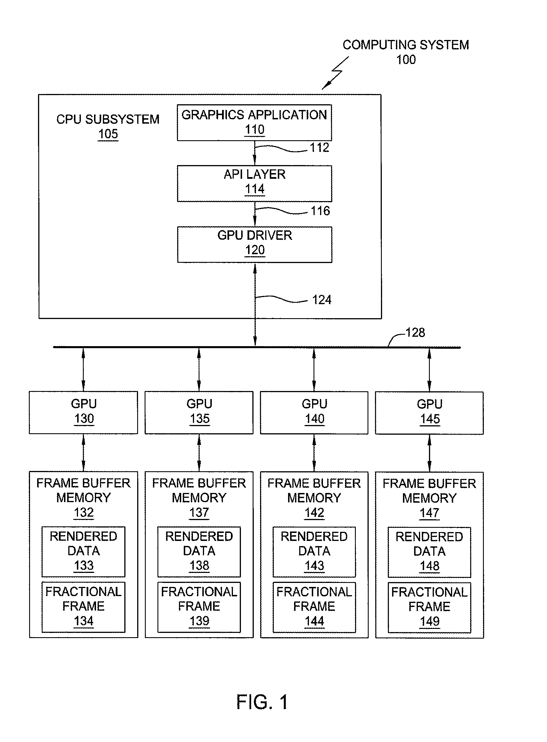
[0017]FIG. 1 is a conceptual diagram of a multi-GPU computing system 100 that may be used for performing distributed rendering of texture data according to one embodiment of the invention. The system 100 may include a central processing unit (CPU) subsystem 105 and two or more GPUs (four are shown) 130, 135, 140, 145. The CPU subsystem 105 may include the necessary well-known hardware and software elements to support a typical software application environment. A graphics app...


PUM


Abstract

A method and apparatus for distributing the workload of rendering an image where texture mapping is involved among multiple graphics processing units (GPUs) are provided. The method generally entails dividing a texture map among multiple GPUs, performing texture mapping in each GPU to render image data in each GPU's frame buffer, combining the image data from each frame buffer, and scanning out the combined image to a display.

Description

BACKGROUND OF THE INVENTION[0001]1. Field of the Invention[0002]Embodiments of the present invention generally relate to graphics processing and, more particularly, to rendering images on systems with multiple graphics processing units (GPUs).[0003]2. Description of the Related Art[0004]Computer graphics image data typically undergoes several processing steps before each graphics frame is completely rendered for display or storage. Each processing step typically operates on graphics image data utilizing programming steps defined through an application programming interface (API), enabling the graphics application to utilize high performance hardware, such as a graphics processing unit (GPU), to execute a set of processing steps with minimal real-time supervision from a host central processing unit (CPU). For example, a software application executing on the host CPU may use an API to program processing steps in a GPU including physics, geometric transform, polygon setup, rasterizatio...

Claims


Application Information

Patent Timeline
Patent Type & Authority Patents(United States)
IPC IPC(8): G06F15/16G09G5/36
CPCG06T15/04G06T2210/52
Inventor BIERMANN, RALFLICHTENBELT, BARTHOLD B.CUNNIFF, ROSS A.JULIANO, JEFFREY F.BOLZ, JEFFREY A.
Owner NVIDIA CORP
Why Eureka
Try Eureka