Image heating apparatus including a belt member for heating an image on a recording material

a heating apparatus and image technology, applied in the direction of ohmic resistance heating, electrographic process apparatus, instruments, etc., can solve the problems of non-uniform temperature, decrease in the heating efficiency of the belt corresponding to the amount of heat generated, and decrease in the amount of heat generation around the metal member, so as to reduce the heating efficiency attributable to the inside metal member

Active Publication Date: 2011-06-28
CANON KK
View PDF23 Cites 8 Cited by
  • Summary
  • Abstract
  • Description
  • Claims
  • Application Information

AI Technical Summary

Benefits of technology

[0007]Accordingly, it is a principal object of the present invention to provide an image heating apparatus in which a magnetic flux generated by the coil disposed outside a belt is used to generated heat and in which the adverse influence of the magnetic flux having penetrated into the inside of the belt, which influence is imparted on the member disposed inside the belt, is reduced so that decrease of the heating efficiency attributable to the inside metal member is reduced.

Problems solved by technology

If this occurs, the problem with this structure is not limited to the heat generation of the unintended metal member, but also includes a decrease in the belt-heating efficiency corresponding to the amount of heat generated in the metal member, and / or, a decrease in the amount of heat generation around the metal member with the result of a non-uniformity in the temperature.

Method used


Image

  • Image heating apparatus including a belt member for heating an image on a recording material
  • Image heating apparatus including a belt member for heating an image on a recording material
  • Image heating apparatus including a belt member for heating an image on a recording material

Examples


embodiment 1

(1) Example of Image Forming Apparatus

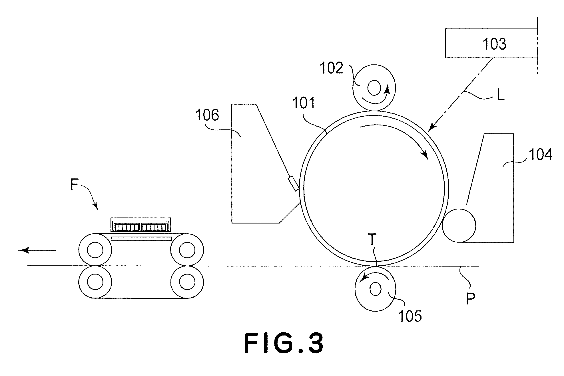
[0023]FIG. 3 is a schematic drawing of an image forming apparatus in which an image heating apparatus in accordance with the present invention is mountable as a fixing apparatus, showing the general structure thereof. This image forming apparatus is a laser beam printer which uses an electrophotographic image formation process.

[0024]Designated by reference numeral 101 is a photosensitive drum as an image bearing member. The photosensitive drum 101 is made up of a cylindrical substrate formed of aluminum, nickel, or the like, and a layer of photosensitive substance, such as OPC, amorphous Selenium, or amorphous Silicon, coated on the peripheral surface of the cylindrical substrate. The photosensitive drum 101 is rotationally driven in the clockwise direction indicated by an arrow mark. As the photosensitive drum 101 is rotated, first, its peripheral surface is uniformly charged by a charge roller 102 as a charging apparatus. Next, the uniformly c...

embodiment 2

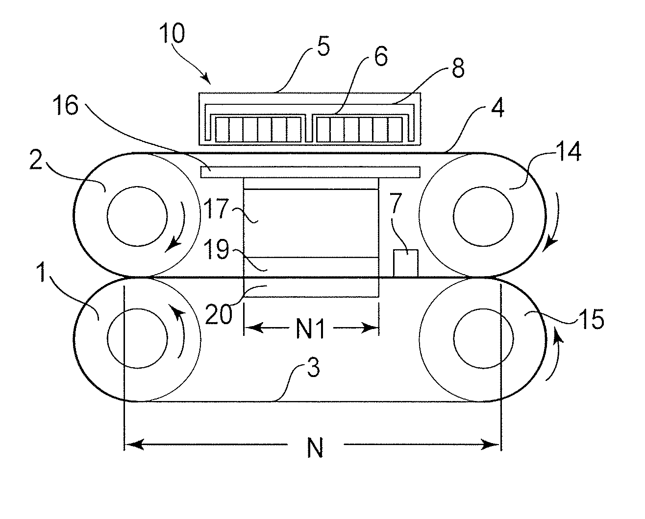
[0048]FIG. 4 is a schematic vertical cross-sectional view of the fixing apparatus in this embodiment.

[0049]The members and portions of this fixing apparatus, which are the same as those of the fixing apparatus in the first embodiment, are given the same referential symbols as those given to describe the first embodiment, and will not be described here. This arrangement regarding the referential symbols also applied to the third to fifth embodiments.

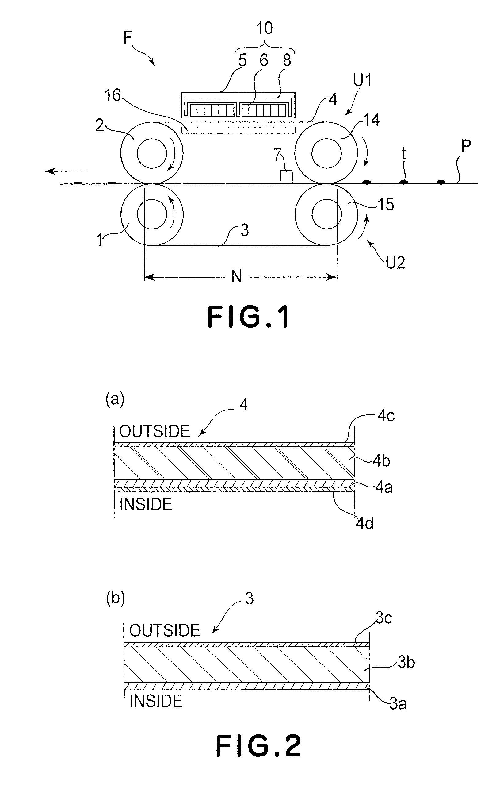
[0050]The fixing apparatus F in this embodiment has a stay 17, which is disposed on the inward side of the fixation belt loop, and to which the components to be disposed on the inward side of the fixation belt loop are attached. The stay 17 is supported at this lengthwise ends by the pair of lateral plates of the fixing apparatus F. To the bottom surface of this stay 17, that is, the surface of the stay 17, which is on the nip side, a fixation pad 19 is attached. The fixation belt 4 and pressure belt 3 are pinched by this fixation pad 19,...

embodiment 3

[0057]FIG. 6 is a schematic vertical cross-sectional view of one of the fixing apparatus in this embodiment. FIG. 7 is a schematic vertical cross-sectional view of the other of the fixing apparatus in this embodiment.

[0058]The fixing apparatus F in this embodiment has the modified version of the heat concentration member 16 in the second embodiment; the heat concentration member 16 in the second embodiment has been devised in shape to be rendered more rigid.

[0059]The length of the heat concentration member 16 is the same as the dimension of the fixation belt 4 in the lengthwise direction. Therefore, it is possible that the heat concentration member 16 will warp or bend across its center portion in terms of the lengthwise direction. It is also possible that the heat concentration member 16 will be difficult to handle when assembling the fixing apparatus F.

[0060]In this embodiment, therefore, the heat concentration member 16 is formed as an integral part of the stay 17, preventing the...


PUM


Abstract

An image heating apparatus includes an endless belt for heating an image on a recording material at a nip; magnetic flux generating means, disposed opposed to an outer surface of the endless belt, for generating a magnetic flux to cause the belt to generate heat; a metal member disposed inside the belt and supporting a member which is disposed inside the belt; and a magnetic flux reducing member, disposed between the metal member and an opposing portion of the belt which is opposed to the magnetic flux generating means, for reducing a magnetic flux actable on the metal member.

Description

FIELD OF THE INVENTION AND RELATED ART[0001]The present invention relates to an image heating apparatus for heating an image on a recording material. An image heating apparatus is usable as a fixing apparatus in which an unfixed image formed on a recording material is fixed, and a glossiness applying apparatus in which an image fixed on a recording material is heated to improve the glossiness of the image, and so on.[0002]An image forming apparatus such as a copying machine or a printer comprises an image forming station, and an image heat-fixing apparatus for heating and fixing the toner image formed by the image forming station on the recording material into a permanent fixed image.[0003]Recently, in the field of an image heat-fixing apparatus, an electromagnetic-induction-heating-type fixing apparatus has been put into practice in place of a fixing apparatus of a heating-roller type having a halogen lamp as a heating source, since the electromagnetic-induction-heating-type fixing...

Claims


Application Information

Patent Timeline
Patent Type & Authority Patents(United States)
IPC IPC(8): G03G15/20
CPCG03G15/2039
Inventor SUZUKI, HITOSHI
Owner CANON KK
Why Eureka
Try Eureka