Model based sensor system for loads aware control laws

a sensor system and load-aware technology, applied in the field of model-based virtual sensor system, can solve the problems of inability to operate instruments in a field environment, increase in aircraft weight,

Inactive Publication Date: 2011-06-28
SIKORSKY AIRCRAFT CORP
View PDF17 Cites 18 Cited by
  • Summary
  • Abstract
  • Description
  • Claims
  • Application Information

AI Technical Summary

Problems solved by technology

Although effective, aircraft weight is concomitantly increased.
Although direct measurement through a specially instrumented rotor hub having a sensor system within the rotating frame typical of flight test instrumented aircraft is conventionally utilized, such instrumentation may not be practical for operations in a field environment.

Method used


Image

  • Model based sensor system for loads aware control laws
  • Model based sensor system for loads aware control laws
  • Model based sensor system for loads aware control laws

Examples


Embodiment Construction

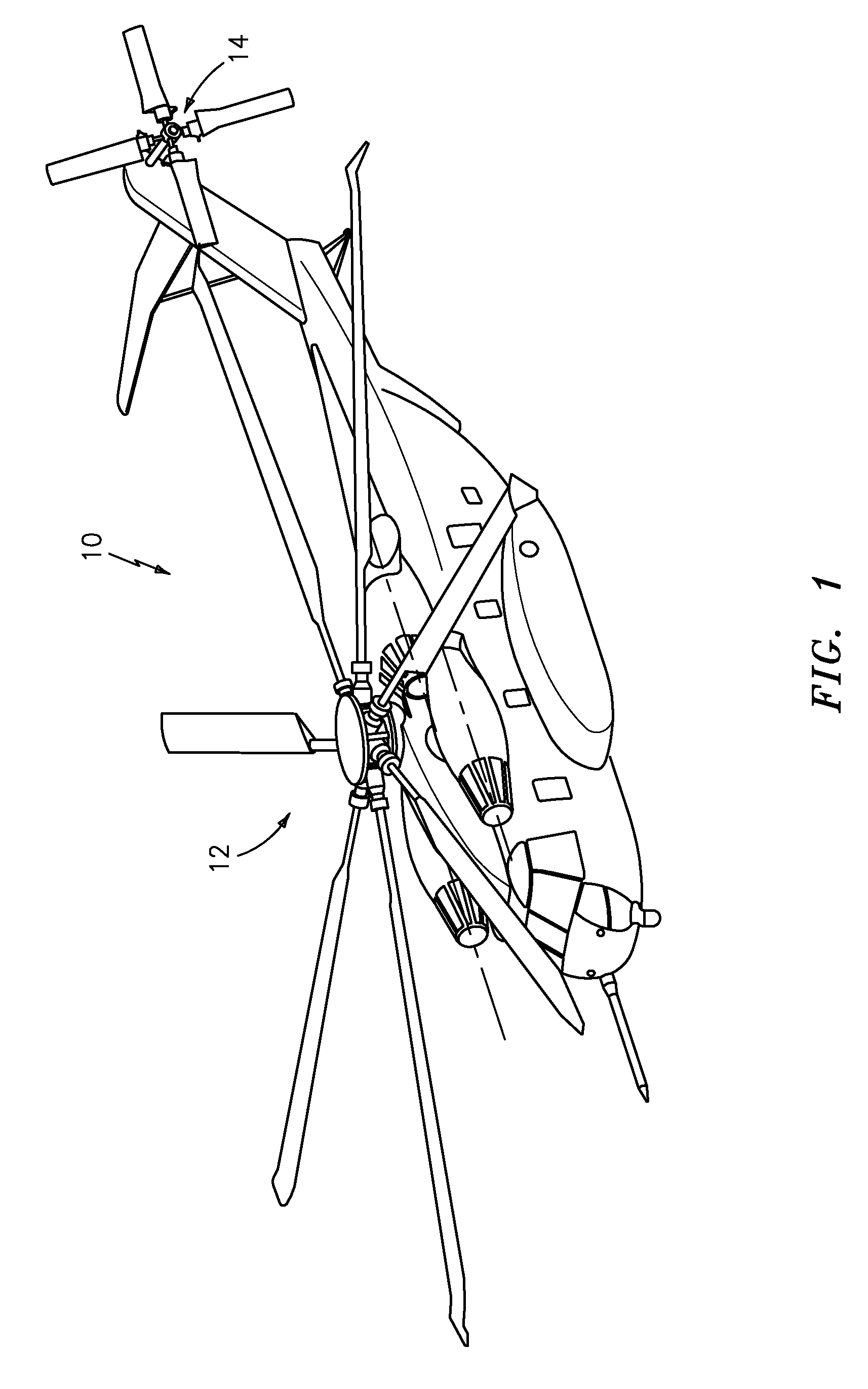
[0018]FIG. 1 illustrates a general perspective view of a helicopter embodiment 10 of a rotary wing aircraft for use with the present invention. The helicopter includes a main rotor assembly 12 and tail rotor assembly 14. Although a particular helicopter configuration is illustrated and described in the disclosed embodiment, other configurations and / or machines, such as high speed compound rotary wing aircraft with supplemental translational thrust systems, dual contra-rotating, coaxial rotor system aircraft, turbo-props, tilt-rotors and tilt-wing aircraft, will also benefit from the present invention.

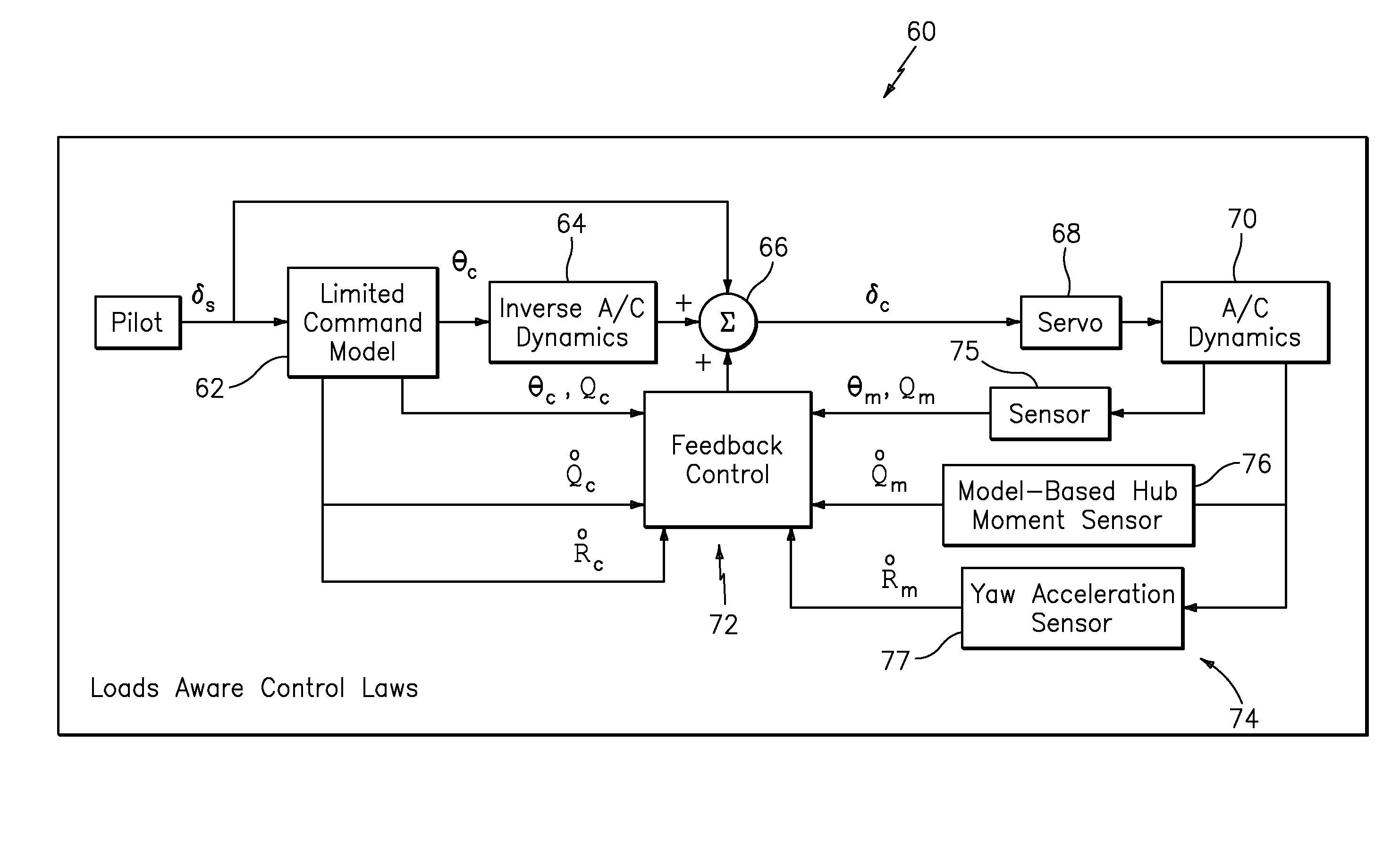
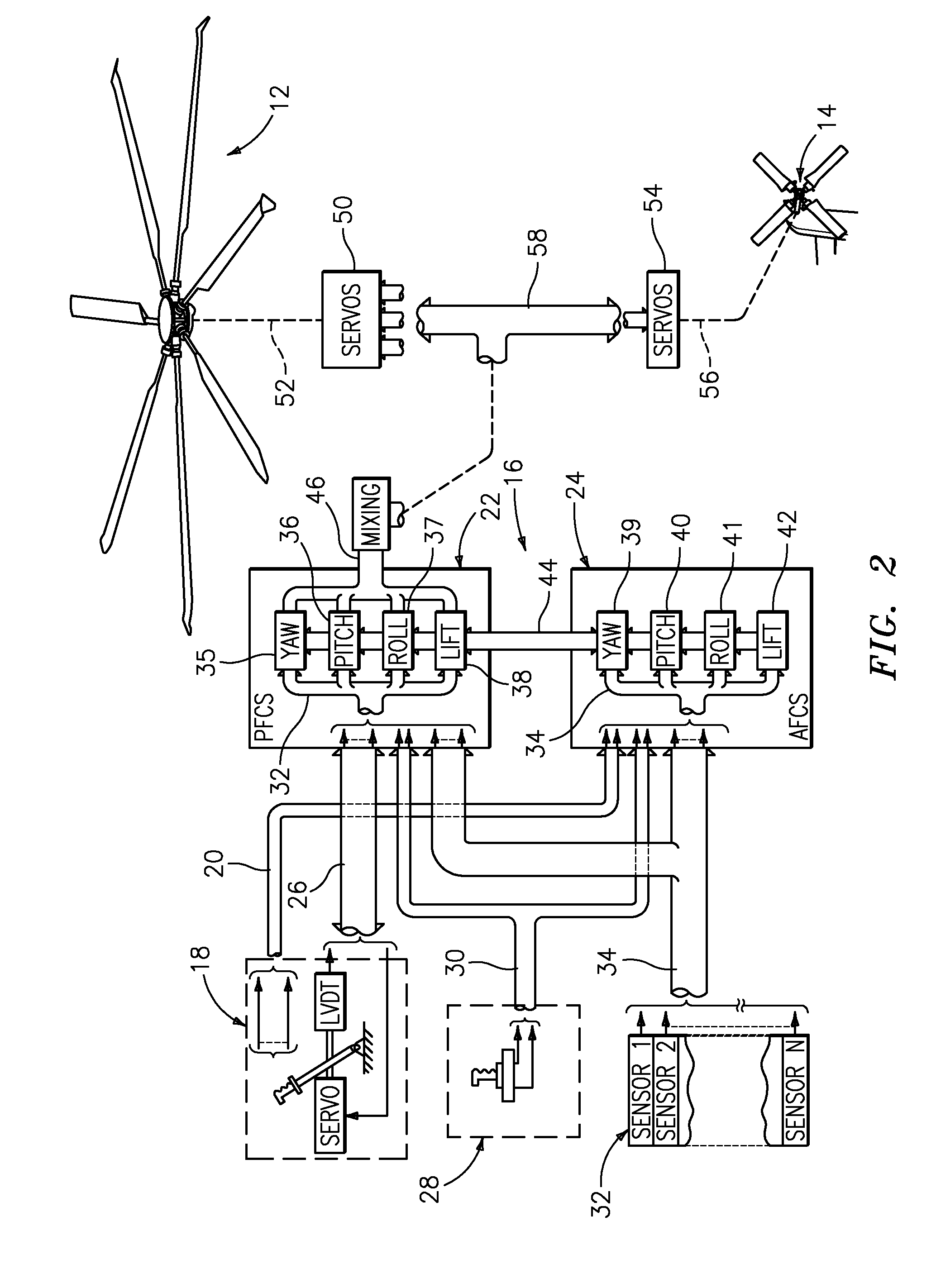
[0019]Referring to FIG. 2, a fly-by-wire type flight control system 16 includes a model following control system which shapes the pilot's controller and displacement commands through an inverse vehicle model to produce the desired aircraft response. The system includes a Primary Flight Control System (PFCS) 22 and a Automatic Flight Control System (AFCS) 24. The PFCS 22 and AFCS 24 each...


PUM


Abstract

A flight control system includes a model-based sensor system which estimates angular accelerations to control rotor system moment such that loads on the aircraft structure are reduced to thereby allow an aircraft structural envelope to more closely follow an aircraft service flight envelope.

Description

BACKGROUND OF THE INVENTION[0001]The present invention relates to an aircraft model-based sensor system, and more particularly to a model-based virtual sensor system for calculation of angular acceleration from measured dynamic quantities that are available in a flight control computer for subsequent utilization in feedback flight control systems to reduce aircraft flight loads while maintaining maneuvering performance.[0002]The structure of a rotary-wing aircraft is designed to withstand flight loads that occur during all phases of aircraft operation such as aerodynamic forces and moments from the fuselage and the rotor system. Flight loads typically peak during maneuvering flight. An aircraft structural envelope is designed relative an aircraft Operational Flight Envelope (OFE) and Service Flight Envelope (SFE) with a margin to more than accommodate peak flight loads. The margin is often provided by reinforced aircraft structure. Although effective, aircraft weight is concomitantl...

Claims


Application Information

Patent Timeline
Patent Type & Authority Patents(United States)
IPC IPC(8): G05D1/00
CPCG05D1/0858B64C27/57
Inventor SAHASRABUDHE, VINEETFAYNBERG, ALEX
Owner SIKORSKY AIRCRAFT CORP
Why Eureka
Try Eureka