

Dynamic matrix sensitivity measuring instrument for inertial sensors, and measuring method therefor
a technology of inertia sensor and dynamic matrix, which is applied in the direction of instruments, pedestrian/occupant safety arrangements, vehicular safety arrangements, etc., can solve the problems of calibration techniques, device limitations to one-dimensional motion, and the state of affairs has not fully satisfactorily established a method for evaluating the performance of acceleration sensors or perfected a measurement standard
- Summary
- Abstract
- Description
- Claims
- Application Information
AI Technical Summary
Benefits of technology
Problems solved by technology
Method used
Image

Examples
example 1
[0090] First, as Example 1, the case of adopting a one-axis accelerometer as the accelerometer 1 subject to calibration and using a three-dimensional motion generating machine will be explained.
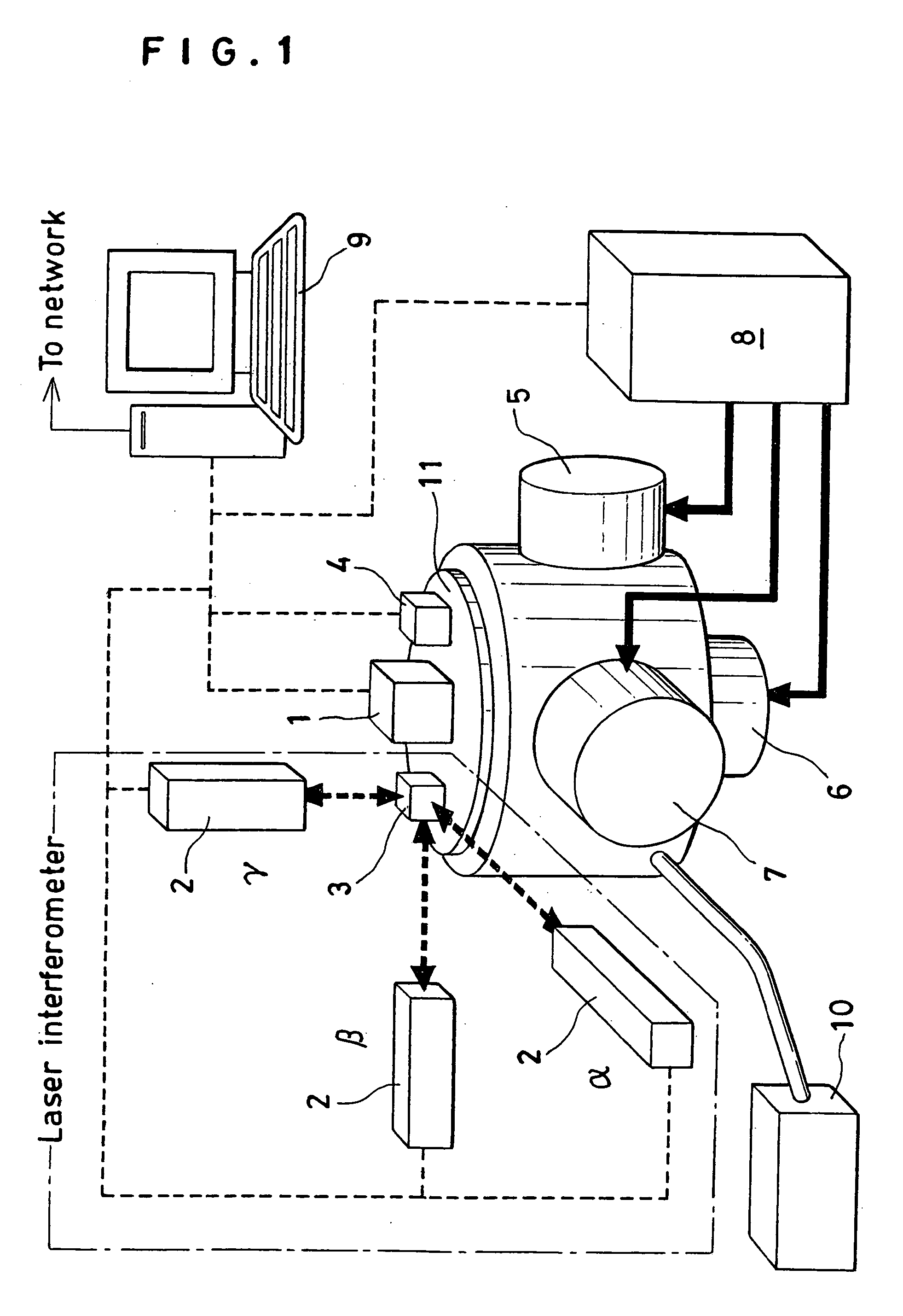
[0091] The operating part of the processor 9 is manipulated to transmit control signals to the individual actuators 5, 6 and 7 which are sources of vibration so that the tables of these motion generating machines may generate respectively prescribed motions. At this time, the inertia sensor 4 for controlling the motion generating machine makes measurement through the table 11 to judge whether or not the individual actuators 5, 6 and 7 are operating with prescribed vibrations and the processor 9 generates a control signal based on the difference between the waveform of the target motion of the table and the actually measured waveform and transmits control signals to the individual actuators 5, 6 and 7 so that the actuators 5, 6 and 7 may produce prescribed vibrations.
[0092] Thus, the prescri...
example 2
[0102] Example 2 represents the case of adopting a two-axis accelerometer as the accelerometer 1 subject to calibration and using a three-dimensional motion generating machine. The output signals of the accelerometer 1 are input to the processor 9 by using the two sensitivity axes of the accelerometer 1 as X axis and Y axis. The processor 9 subjects the output signals to Laplace transform and consequently obtains (aox(jω), aoy(jω), 0). The letter ω denotes the angular frequencies. The Z axis component is zero of course. Similarly, the laser interferometer 2 measures the input acceleration of the accelerometer 1 and the processor 9 subjects the input acceleration to Laplace transform and consequently obtains (aix(jω), aiy(jω), aiz(jω)). It is not stipulated that the input acceleration falls on a plane (sensitivity plane) determined by the two sensitivity axes of the accelerometer 1. When this stipulation is accepted, it does not result in supporting a conclusion that the input accele...
example 3
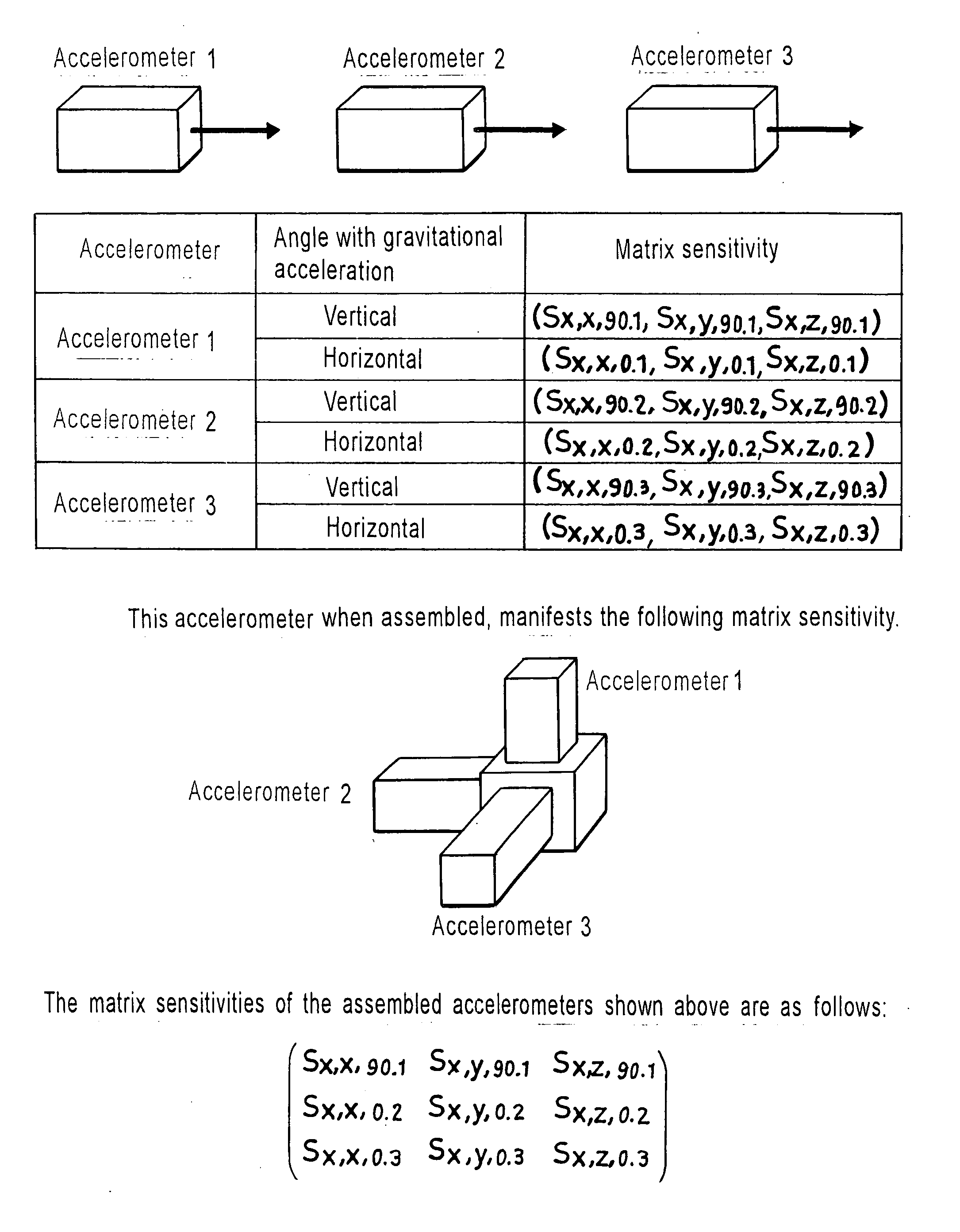
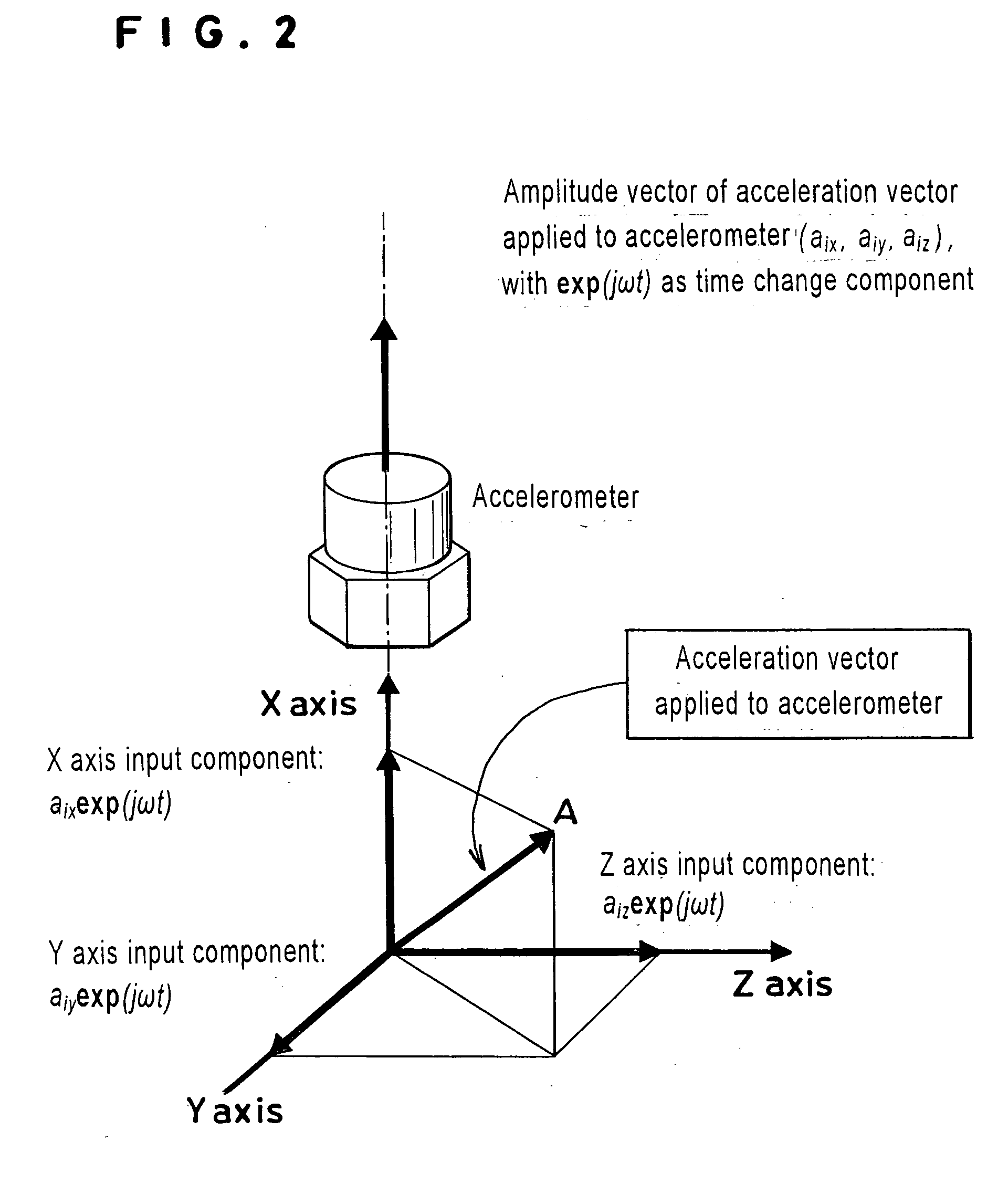
[0113] Example 3 represents the case of adopting a three-axis accelerometer as the accelerometer 1 (inertia sensor) subject to calibration and using a three-dimensional motion generating machine. The output signals of the accelerometer 1 are input to the processor 9 by using the three sensitivity axes of the accelerometer 1 as the inertia sensor, i.e. X axis, Y axis and Z axis. The processor 9 subjects the output signals to Laplace transform and consequently obtains (aox(jω), aoy(jω), aoz(jω)). The letter to denotes the angular frequencies.
[0114] Similarly, the laser interferometer 2 measures the input acceleration of the accelerometer 1 and the processor 9 subjects the input acceleration to Laplace transform and consequently obtains (aix(jω), aiy(jω), aiz(jω)). It is not stipulated generally that the input acceleration falls on a vector space (sensitivity space) determined by the three sensitivity axes of the accelerometer. When this stipulation is accepted, it does not result in ...
PUM
 Abstract
Description
Claims
Application Information