Method of and apparatus for correction of coordinate measurement errors due to vibrations in coordinate measuring machines (cmms)

a technology of coordinate measuring machine and vibration, applied in the direction of acceleration measurement using interia force, instruments, navigation instruments, etc., can solve the problems of high thermal coefficient of bias and scale factor, high cost of accelerometer, and undesirable characteristics of open-loop configuration accelerometer

Inactive Publication Date: 2005-03-15
RENISHAW PLC
View PDF9 Cites 43 Cited by
  • Summary
  • Abstract
  • Description
  • Claims
  • Application Information

AI Technical Summary

Problems solved by technology

This configuration is normally used in highly accurate inertial navigation systems that requires high sensitivity and at the same time cannot tolerate errors in offset bias (drift) and linearity.
However, these accelerometers are expensive.
Open loop configuration accelerometers have the undesirable characteristics of being sensitive to supply voltage variation, non-linearity of the output, and high thermal coefficients of bias and scale factor.
However, the performance will not approach that of a closed loop accelerometer.

Method used


Image

  • Method of and apparatus for correction of coordinate measurement errors due to vibrations in coordinate measuring machines (cmms)
  • Method of and apparatus for correction of coordinate measurement errors due to vibrations in coordinate measuring machines (cmms)
  • Method of and apparatus for correction of coordinate measurement errors due to vibrations in coordinate measuring machines (cmms)

Examples


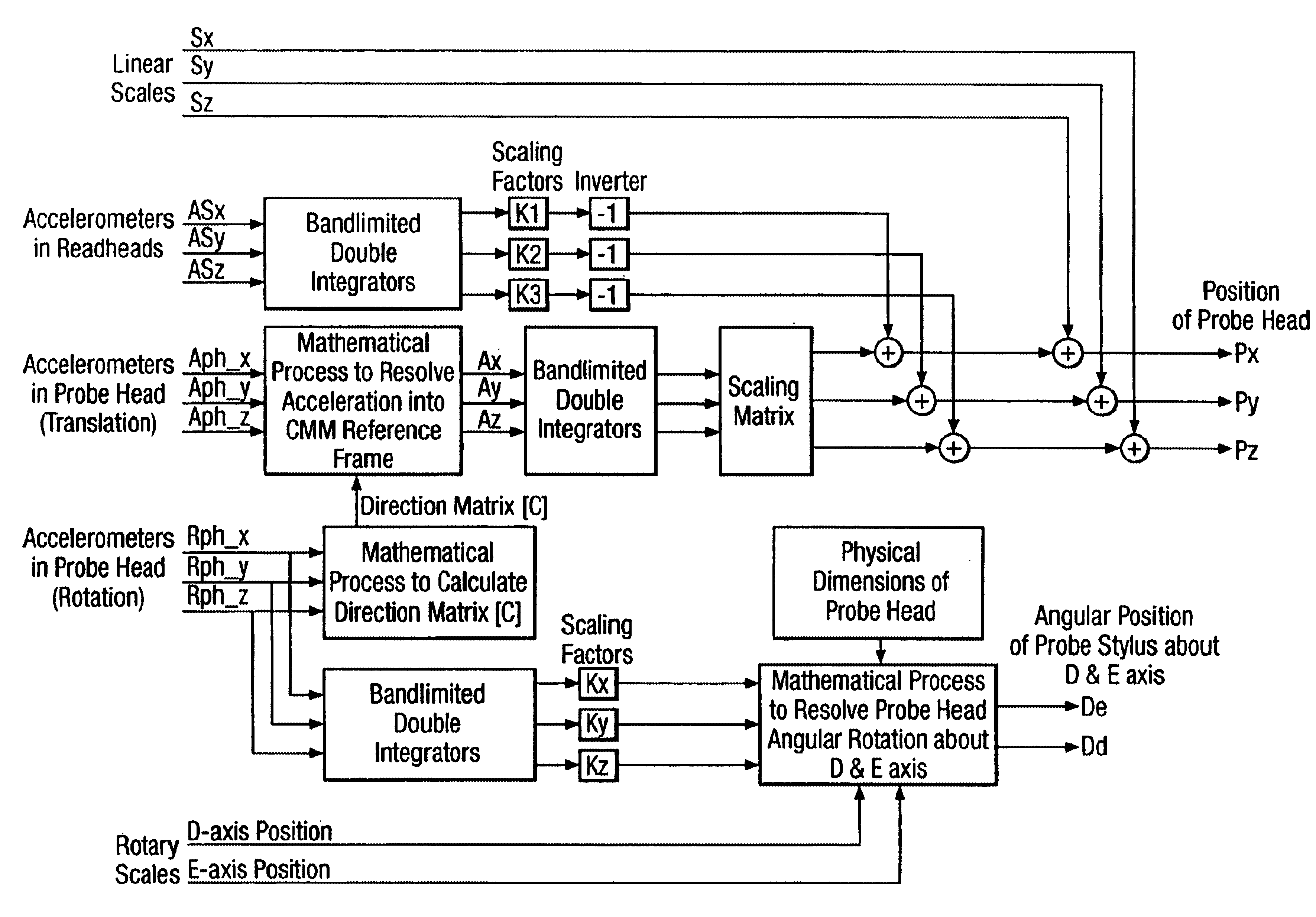
Embodiment Construction

Theoretical Background

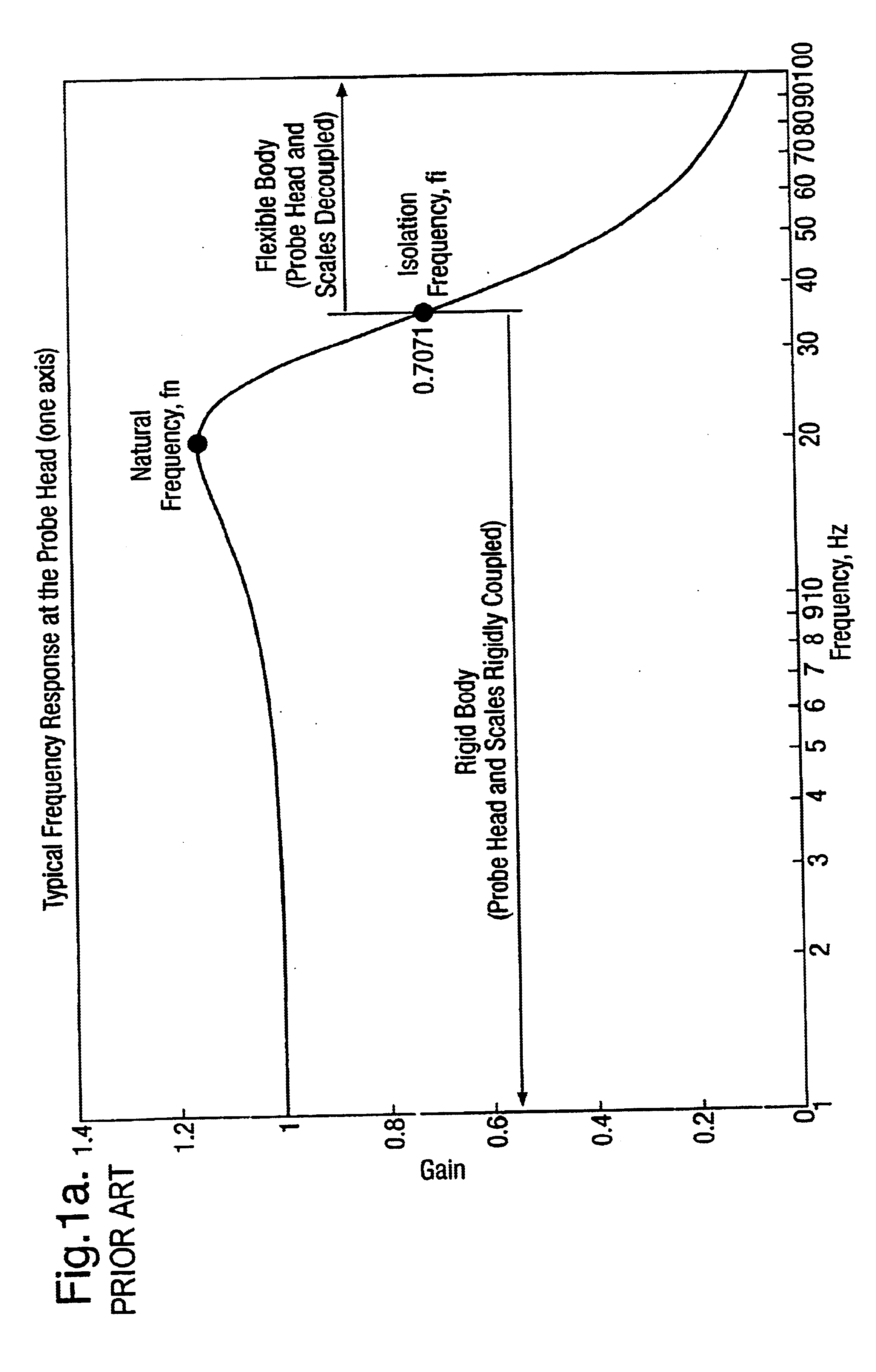
The dynamic response of the probe head mounted on a CMM with a flexible structure will exhibit a typical behaviour frequency response as shown in FIG. 1a, this is an ideal frequency response of displacement between the probe head and the measurement scales. The values and shape of this frequency response is unique to a particular axis of a particular CMM. Frequency response identification is normally carried out as part of a CMM installation procedure to aid in “tuning” the servo system, and there are many common and well established methods for performing frequency response identification. The frequency response of the probe head in a particular axis can be obtained by performing a frequency response identification between the probe head velocity (measured using accelerometers) and velocity obtained from the measurement scale for that axis, this will show the frequency region where the probe head is rigidly coupled to the scale.

Correcting Translational Measure...


PUM


Abstract

Accelerations of a probe or probe head due to vibrations of a machine during a measuring operation are measured using accelerometers placed in the probe or probe head. The acceleration signals are double integrated to determine the corresponding displacements of the probe or probe head and these are added to the readings of displacement of the machine taken from the machine scales using a data fusion algorithm to correct the scale readings for the vibration of the probe. Both linear and angular accelerations of the probe can be corrected in this way.

Description

BACKGROUND OF THE INVENTION1. Field of InventionThe present invention relates to the correction of coordinate measuring errors in CMMs due to vibrations of the component parts thereof.2. Description of the Related ArtU.S. Pat. Nos. 5,594,668 & 5,610,846, both assigned to Carl-Zeiss of Germany describe methods that use machine acceleration information with the aid of correction tables to determine the amount of displacement of the probe head due mainly to probing force.In accordance with the description in these patents, the acceleration information in the three translation directions is obtained by double differentiating scale information. This gives the acceleration of the CMM at the measurement scales and not at the probe head.Also in the methods described in the above-mentioned patents, a correction table containing prior knowledge of the bending behaviour of a particular CMM due to various accelerations and velocities at various positions is used to provide a correction to measu...

Claims


Application Information

Patent Timeline
Patent Type & Authority Patents(United States)
IPC IPC(8): G01B21/02G01B21/04G01C21/10G01C21/16G01P15/18G01B21/20
CPCG01C21/16G01B21/045G01C21/183
Inventor NAI, KENNETH CHENG-HOEWRIGHT, DAVID ALLAN
Owner RENISHAW PLC
Why Eureka
Try Eureka