Auxiliary handle attachment for a tool

Active Publication Date: 2011-07-05
PLADSON JAMES M
View PDF18 Cites 23 Cited by
  • Summary
  • Abstract
  • Description
  • Claims
  • Application Information

AI Technical Summary

Benefits of technology

[0008]A system for efficiently decreasing or eliminating the requirement to bend over and cause strain upon ones back when using a long-handled tool, such as a shovel, broom, rake, or the like. The invention generally relates to a tool attachment which includes a mounting structure having a first channel member including a first channel and a second channel member including a second channel aligned with the first channel, an auxiliary shaft extending upwardly from the mounting structure, and an auxiliary handle extending from the shaft. The mounting structure is adapted to attach to the shaft or handle of the tool by collectively receiving the shaft from an upper side of the first channel opposite the first channel member and a lower side of the second channel opposite the second channel member. Various fastening members and grips may also be used to secure the shaft within the channel members of the mounting structure.

Problems solved by technology

This can often result in forcing the individual to extend beyond a comfortable range of motion and cause strain upon one's back.

Method used


Image

  • Auxiliary handle attachment for a tool
  • Auxiliary handle attachment for a tool
  • Auxiliary handle attachment for a tool

Examples


Embodiment Construction

A. Overview

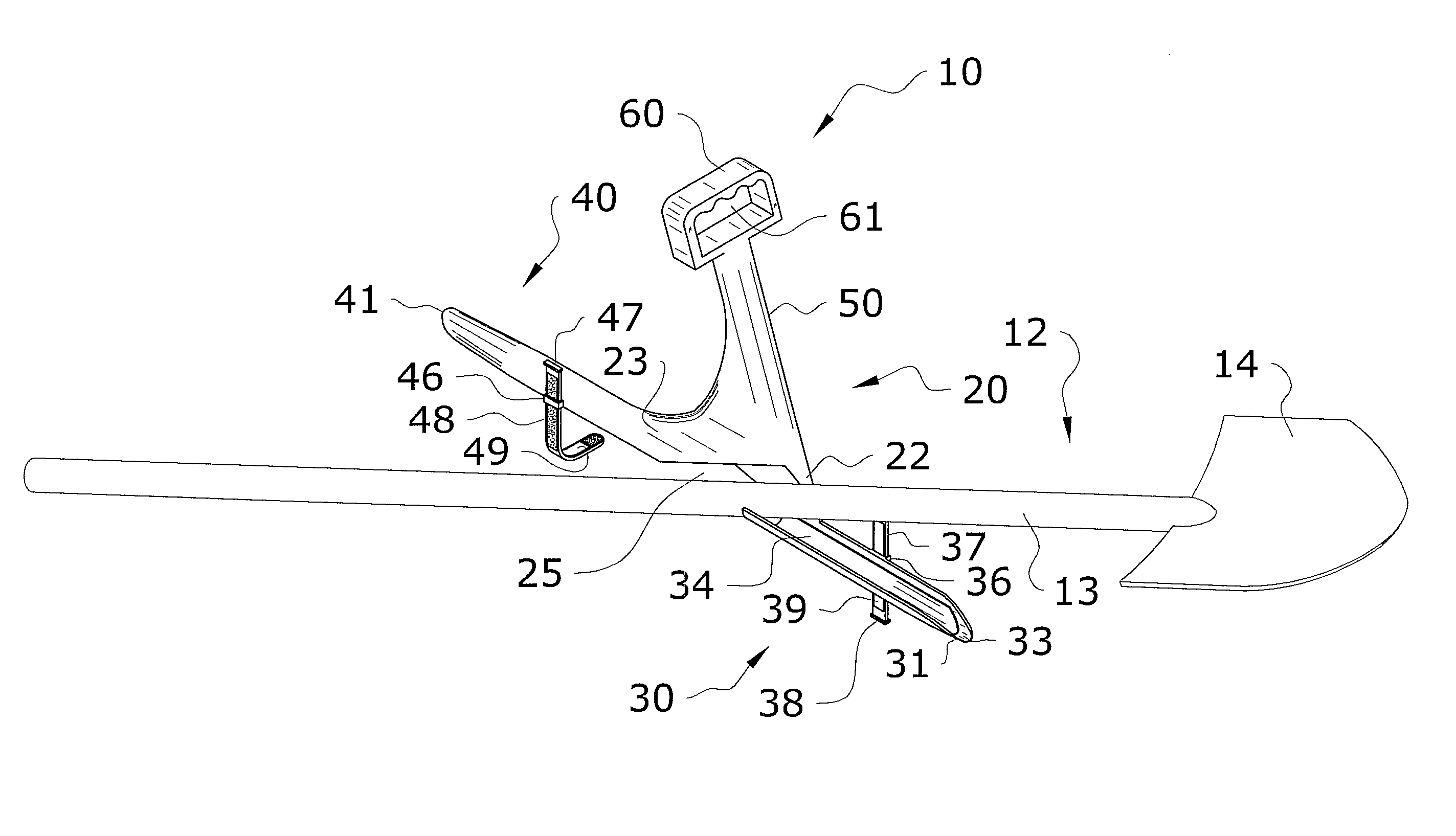
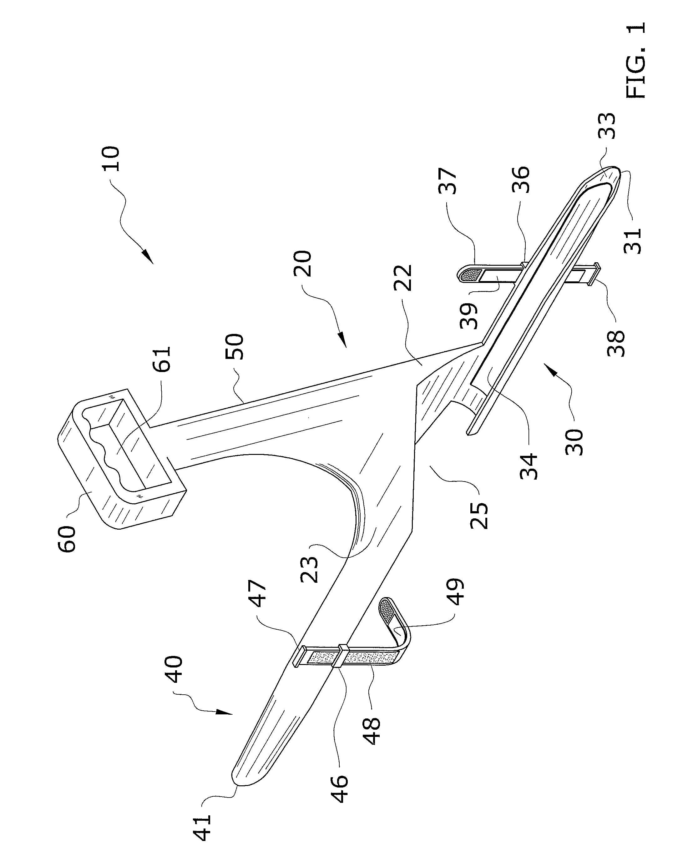
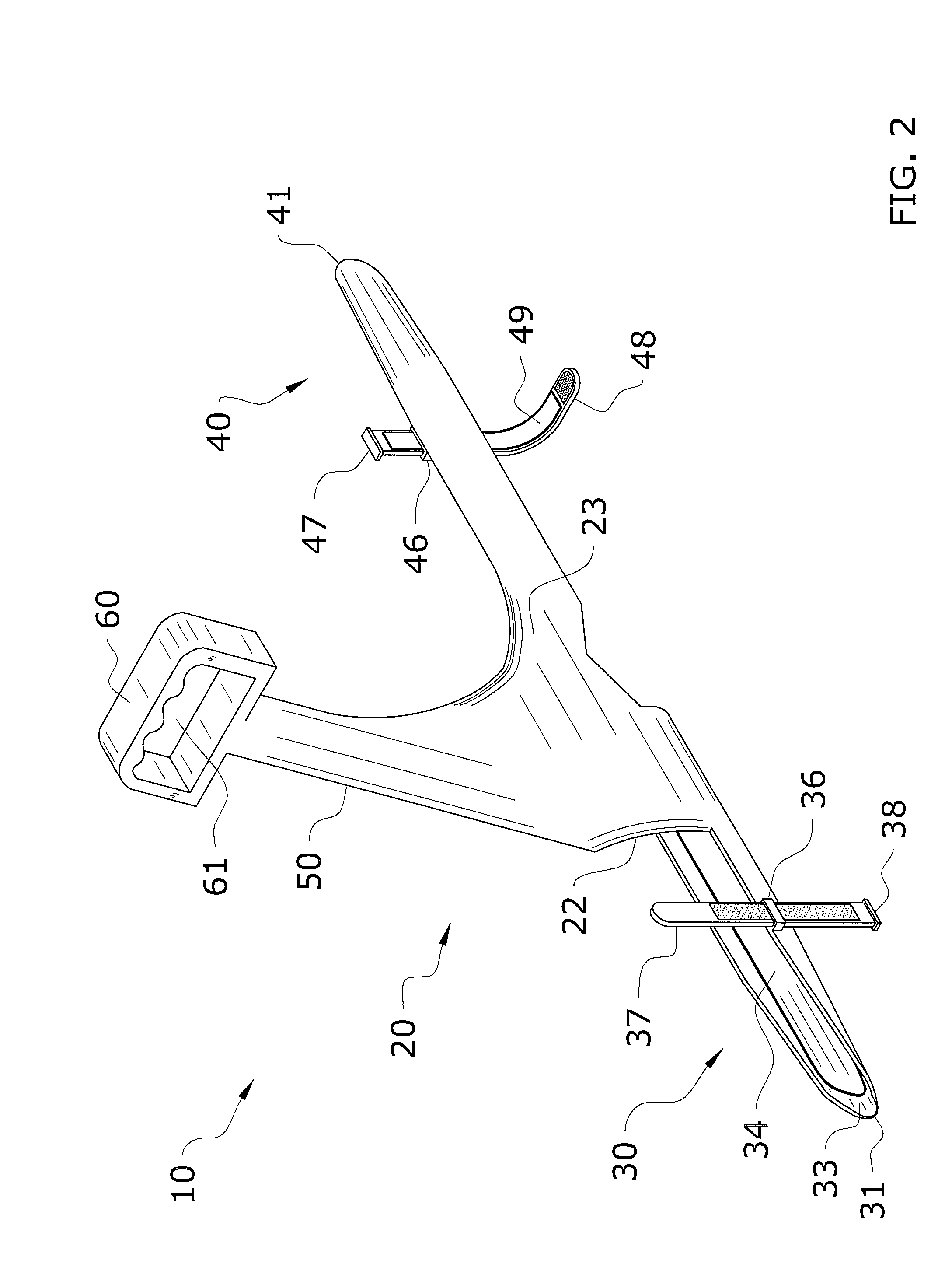
[0024]Turning now descriptively to the drawings, in which similar reference characters denote similar elements throughout the several views, FIGS. 1 through 13 illustrate an auxiliary handle attachment for a tool 10, which comprises a mounting structure 20 having a first channel member 30 including a first channel 33 and a second channel member 40 including a second channel 43 aligned with the first channel 33, an auxiliary shaft 50 extending upwardly from the mounting structure 20, and an auxiliary handle 60 extending from the shaft 13. The mounting structure 20, auxiliary shaft 50, and auxiliary handle 60 are preferably integrally formed in a one-piece structure.

[0025]The mounting structure 20 is adapted to attach to the shaft 13 or handle of the tool 12 by collectively receiving the shaft 13 from an open upper side of the first channel 33 opposite the first channel member 30 and an open lower side of the second channel 43 opposite the second channel member 40. Various ...


PUM


Abstract

An auxiliary handle attachment for efficiently decreasing or eliminating the requirement to bend over and cause strain upon ones back when using a long-handled tool, such as a shovel, broom, rake, or the like. The auxiliary handle attachment generally includes a mounting structure having a first channel member including a first channel and a second channel member including a second channel aligned with the first channel, an auxiliary shaft extending upwardly from the mounting structure, and an auxiliary handle extending from the shaft. The mounting structure is adapted to attach to the shaft or handle of the tool by collectively receiving the shaft from an upper side of the first channel opposite the first channel member and a lower side of the second channel opposite the second channel member. Various fastening members and grips may also be used to secure the shaft within the channel members of the mounting structure.

Description

CROSS REFERENCE TO RELATED APPLICATIONS[0001]Not applicable to this application.STATEMENT REGARDING FEDERALLY SPONSORED RESEARCH OR DEVELOPMENT[0002]Not applicable to this application.BACKGROUND OF THE INVENTION[0003]1. Field of the Invention[0004]The present invention relates generally to a tool attachment and more specifically it relates to an auxiliary handle attachment for a tool for efficiently decreasing or eliminating the requirement to bend over and cause strain upon ones back when using a long-handled tool, such as a shovel, broom, rake, or the like.[0005]2. Description of the Related Art[0006]Any discussion of the related art throughout the specification should in no way be considered as an admission that such related art is widely known or forms part of common general knowledge in the field.[0007]Long-handled tools, such as shovels, brooms, rakes, hoes, and the like are widely use for performing various tasks. Typically, when using the tools, the user must repeatedly bend...

Claims


Application Information

Patent Timeline
IPC IPC(8): A01B1/22B25G3/20
CPCA01B1/026B25G3/24B25G1/00Y10T16/4713B25G1/102
Inventor PLADSON, JAMES M.
Owner PLADSON JAMES M
Why Eureka
Try Eureka