Optical positioner design in X-ray analyzer for coaxial micro-viewing and analysis

a technology of optical positioners and micro-viewers, which is applied in the direction of radiation beam directing means, instruments, and handling using diaphragms/collimeters, etc., can solve the problems of difficult sample analysis, limited design of x-ray optics or the number of x-ray optics immediately available to the user, and the coaxial imaging of samples limits the design of x-ray optics or the effect of immediate placemen

Active Publication Date: 2011-07-05
EDAX
View PDF53 Cites 14 Cited by
  • Summary
  • Abstract
  • Description
  • Claims
  • Application Information

AI Technical Summary

Benefits of technology

[0009]The present invention provides a method and apparatus that allows for coaxial microscopic viewing and X-ray analyzing of a sample that overcomes the deficiencies of the prior art analyzers. In addition, the present invention provides a microscopic X-ray analyzer that allows for multiple X-ray optics to quickly and easily be placed normal to the sample for analysis without moving the sample.
[0014]The X-ray analyzer may further include a second camera positioned to view the sample through a port provided in the body member of the optical positioner assembly. The first camera may be a high-resolution camera and the second camera may be a low-resolution camera. The optical positioner may be positioned by a motive force. The motive force may be provided by a piezoelectric motor or any other suitable motor. The optical positioner may include an optical encoder to provide accuracy in positioning one of the at least one X-ray optic and the optic viewing lens normal to the sample on the sample stage. The optical positioner assembly may further include at least one laser extending through the body for proper positioning of the sample stage.

Problems solved by technology

However, the positioning of the X-ray beam at such an angle introduces some difficulties in the analysis of a sample.
However, this configuration also suffers from various deficiencies.
For instance, the mirror used to allow for coaxial imaging of the sample limits the design of the X-ray optics or the number of X-ray optics immediately available to the user.
Another problem with such a design is that the use of such a mirror may limit the optical image quality or field of view of the sample.
However, the movement of a sample in such a manner may cause a loosely mounted sample to shift while the stage is transitioning between the viewing and analyzing positions.

Method used


Image

  • Optical positioner design in X-ray analyzer for coaxial micro-viewing and analysis
  • Optical positioner design in X-ray analyzer for coaxial micro-viewing and analysis
  • Optical positioner design in X-ray analyzer for coaxial micro-viewing and analysis

Examples


example

[0046]The following example is intended to be illustrative only and is not intended to limit the scope of the invention.

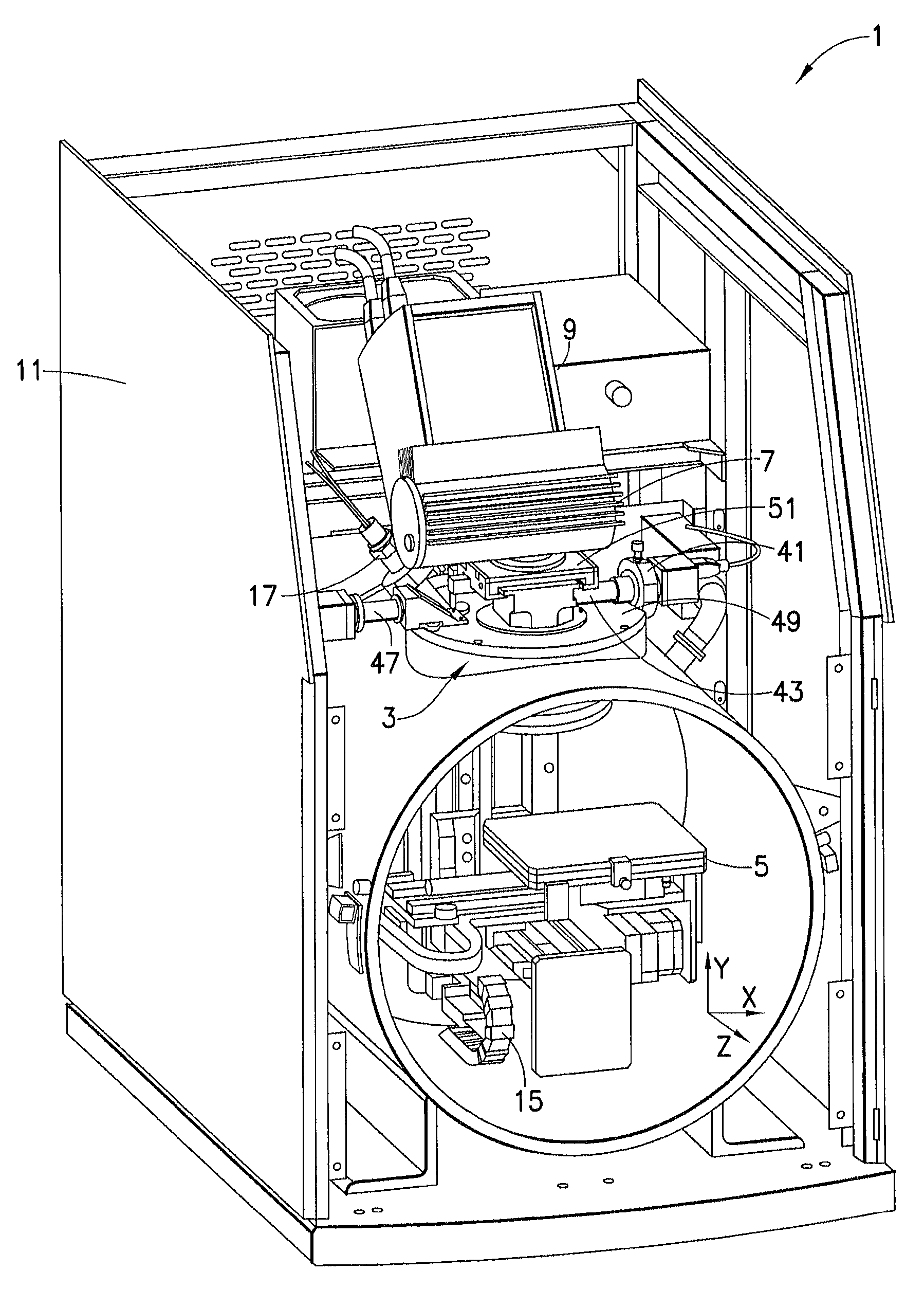
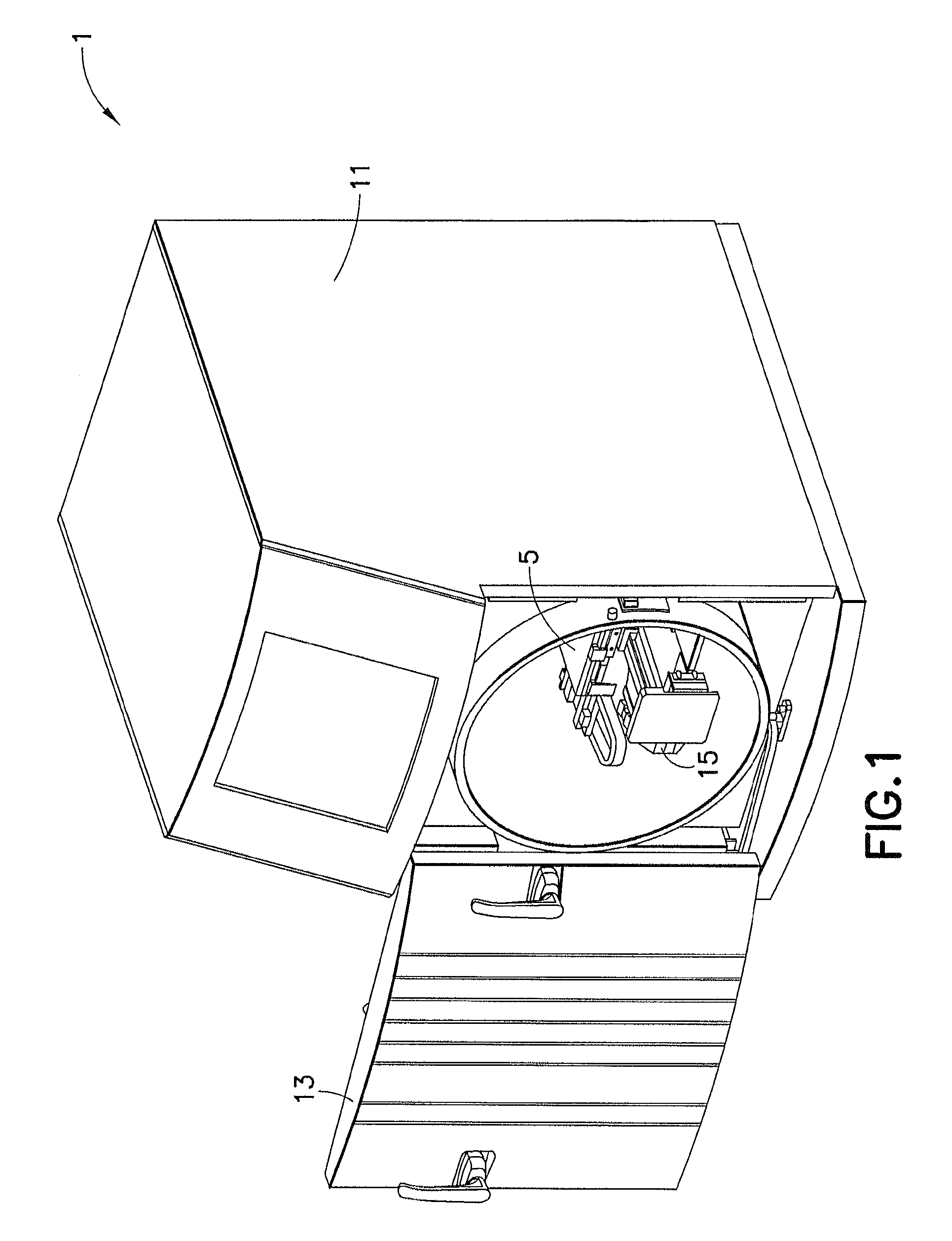
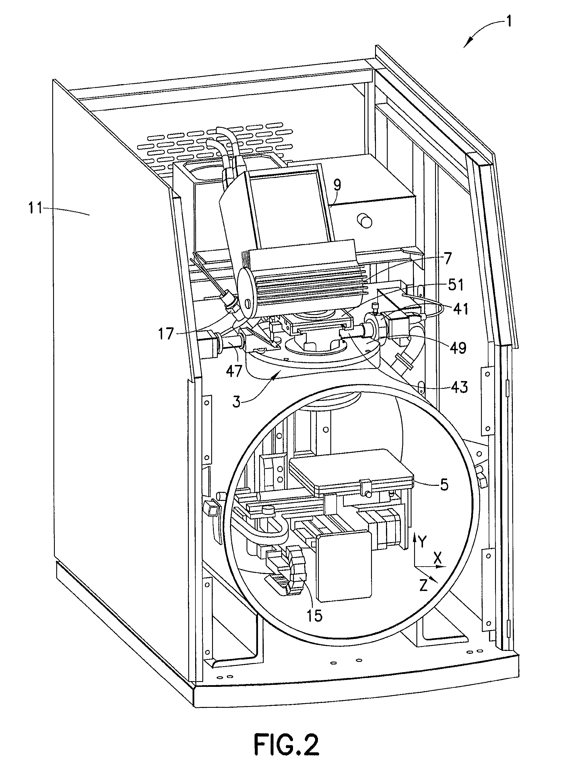
[0047]In order to perform analysis using X-ray analyzer 1 of the present invention, door 13 is opened and a sample or samples are mounted on sample stage 5. The ability of sample stage 5 to move allows for multiple samples to be analyzed or for a single sample to be measured at different points. Optical positioner 31 moves to align the optical viewing lens 37 to view and record images of the sample with the high-resolution camera 41. Sample stage 5 is moved to locate a point, points, or an area to be analyzed. Optical positioner 31 moves to align the X-ray optic 35 suitable for the type of analysis to be normal to the sample. Primary X-rays from X-ray tube 7 pass through the X-ray optic 35 and irradiate the spot on the sample coincident with the video image. X-ray detector 9 collects secondary X-ray spectra from the sample. Based on measurements of the secondary X-...


PUM


Abstract

An X-ray analyzer includes a sample stage for holding and positioning a sample and an optical positioner assembly configured above the sample stage. The optical positioner assembly includes a body member having an opening; an optical positioner located within the opening; and at least one X-ray optic and an optical viewing lens coupled to a first camera. The at least one X-ray optic and the optical viewing lens are secured to the optical positioner. The optical positioner is configured to align one of the at least one X-ray optic and the optic viewing lens normal to the sample on the sample stage such that the sample is irradiated with X-rays through the X-ray optic along a path which is normal to the sample and coaxial with the optic viewing lens receiving light reflected from the sample when the optic viewing lens is positioned normal to the sample.

Description

BACKGROUND OF THE INVENTION[0001]1. Field of the Invention[0002]The present invention, in general, relates to an X-ray and optical analyzing device and, more particularly, to a microscopic X-ray and optical analyzing device for performing material analysis having coaxial viewing and analysis.[0003]2. Description of Related Art[0004]Typically, microscopic X-ray analyzing devices combine an optical microscope with a micro-beam X-ray analyzer for non-destructive sample analysis. This combination allows for elemental imaging analysis such as studying compositional homogeneity of samples. To create an elemental image, a sample is analyzed multiple times, typically as a matrix of points. The individual spectra are incorporated into a database and elemental images are created with pixels calculated based on some property such as X-ray intensity or weight percent. Each image pixel is related to the parent spectrum and a position on the sample.[0005]Prior art microscopic X-ray analyzers posi...

Claims


Application Information

Patent Timeline
Patent Type & Authority Patents(United States)
IPC IPC(8): A61B6/08
CPCG21K7/00G01N23/20G01N23/223
Inventor NICOLOSI, JOSEPH A.WESTERDALE, ROBERTSCRUGGS, BRUCE ELLIOTTPARK, SUN
Owner EDAX
Why Eureka
Try Eureka