Air sampling system having a plurality of air sampling devices with their own flow switches

a technology of air sampling and flow switch, which is applied in the field of devices and methods for collecting air samples, can solve the problems of large variability in the calculated concentration of pathogens, potential health threats to human health, and none of the prior art devices and air sampling methods described above is suitable for monitoring the level of contaminants in the air of a modern clean room

Active Publication Date: 2011-07-05
VALTEK ASSOC INC
View PDF21 Cites 16 Cited by
  • Summary
  • Abstract
  • Description
  • Claims
  • Application Information

AI Technical Summary

Problems solved by technology

However, that is not always the case, as other operations within those industries may generate contaminants that are above acceptable levels and, therefore, must be prevented from escaping the clean room without treatment.
Negative pressure rooms are often used when there is a concern that contaminants in the air in the room may pose a potential health threat to human health in adjacent spaces or the environment.
The patent states that previous sampling devices could not achieve a constant volumetric air flow of better than ±30% relative to a nominal or set-point flow rate, which caused a large variability in calculated concentrations of pathogens.
None of the prior art devices and air sampling methods described above is suitable for monitoring the level of contaminants in the air of a modern clean room.
For example, a volumetric air flow accuracy not better than ±30% relative to a nominal or set-point flow rate, mechanical bellows, and single-location sampling are not sufficient where issues of sample volume accuracy and precision are important at multiple locations in a clean room.
In addition, none of the prior art devices provide the degree of control, monitoring, reporting, modularity, and remote operation required in the modern clean room.
For example, none of the prior art devices and air sampling methods described above utilizes multiple air sampling devices with inline digital flow switches at each air sampling device to separately and simultaneously measure the air flow realized at each individual air sampling device.
Nor do any of the prior art devices and air sampling methods described above provide the ability to simultaneously monitor and control a variable number of air sampling devices placed at different locations in a clean room from a single, central location that is remote from the air sampling devices.

Method used


Image

  • Air sampling system having a plurality of air sampling devices with their own flow switches
  • Air sampling system having a plurality of air sampling devices with their own flow switches
  • Air sampling system having a plurality of air sampling devices with their own flow switches

Examples


Embodiment Construction

[0039]Several preferred embodiments of the invention are described for illustrative purposes, it being understood that the invention may be embodied in other forms not specifically shown in the drawings.

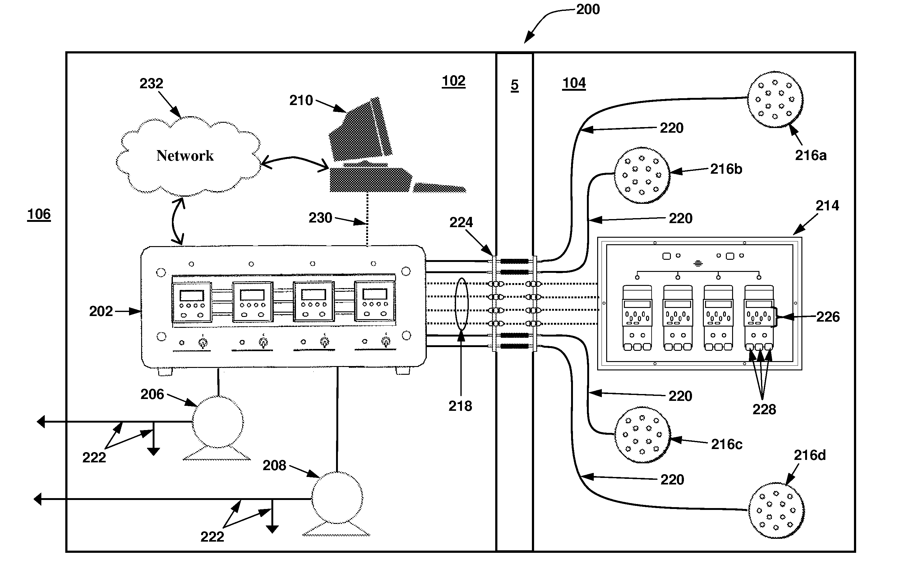
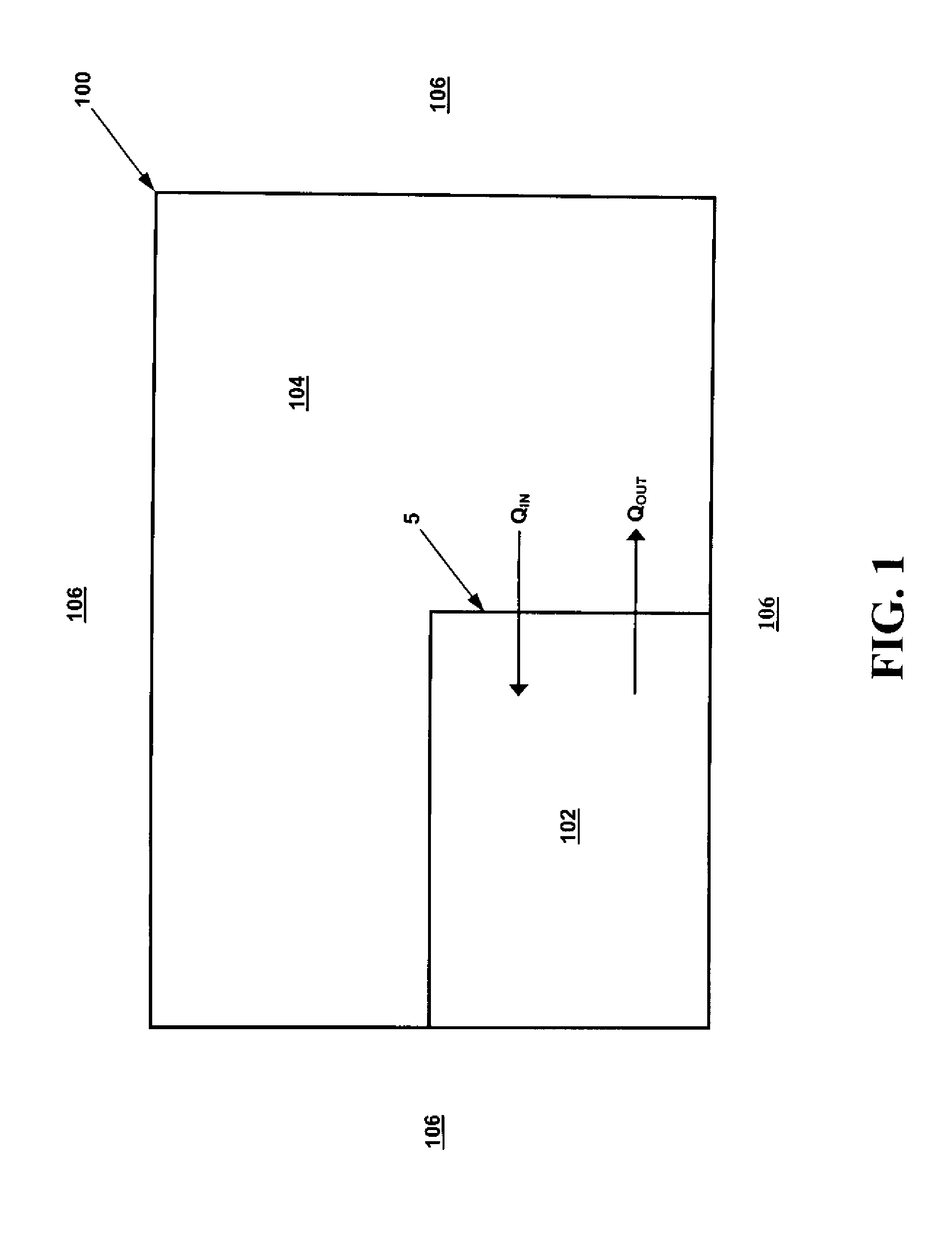
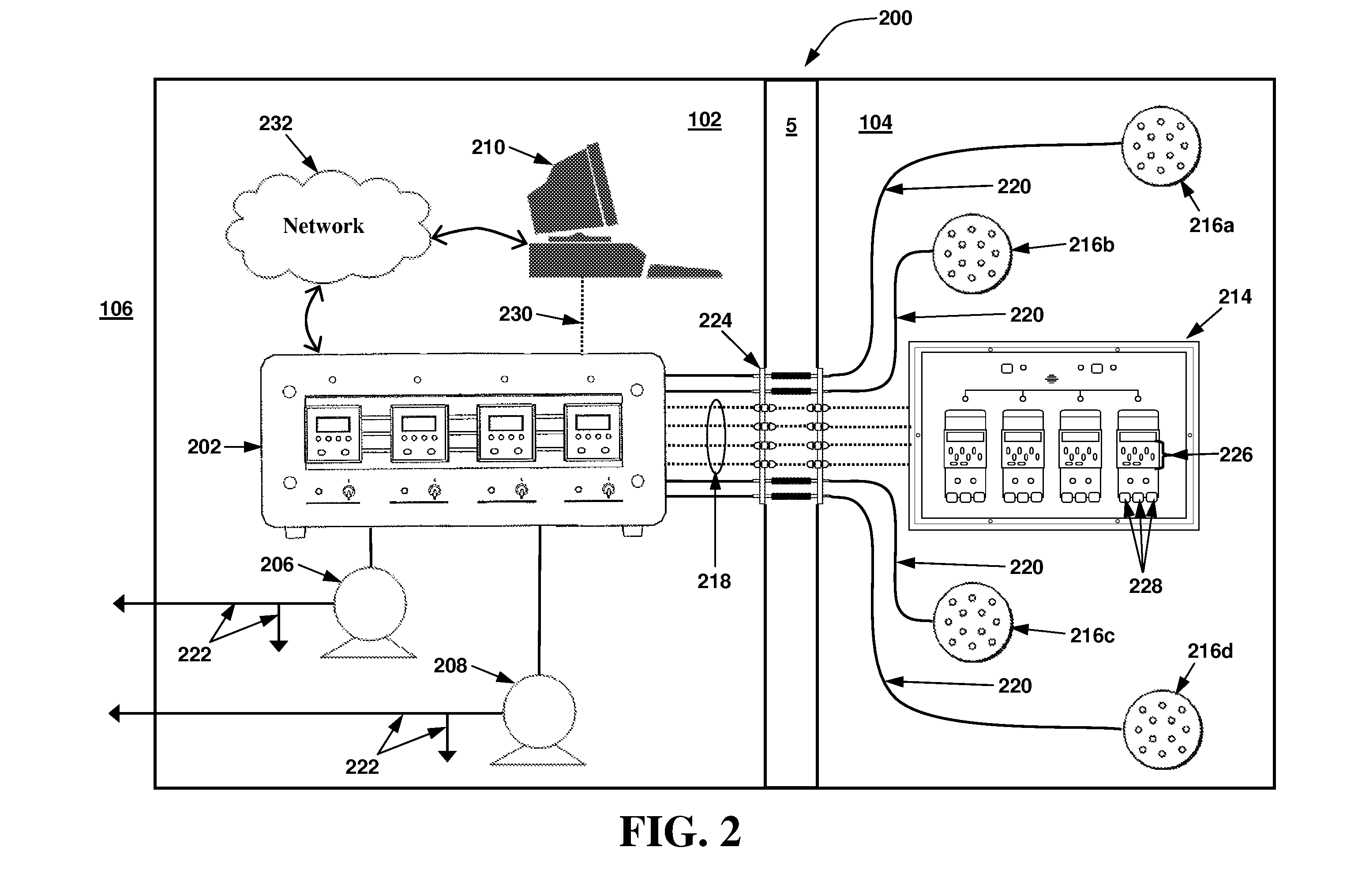
[0040]Turning first to FIG. 1, shown therein is a schematic of an exemplary facility 100 having one or more clean rooms 102 therein. The clean room 102 is surrounded by an adjacent space 104 and the outdoor atmosphere 106. The adjacent space 104 may be one or more rooms within the same facility 100 in which the clean room 102 is located and that adjoin the clean room 102, such as, for example, a separate manufacturing room, another clean room, a finish and fill room, a research laboratory, offices, etc. The clean room 102 and adjacent space 104 are separated by a divider, such as a wall 5.

[0041]The clean room 102 in the exemplary facility 100 is capable of being maintained at an air pressure P1 that is less than or greater than the air pressure P2 of the adjacent space 104 and atmosp...


PUM


Abstract

A system for sampling air in a controlled environment that includes two or more air sampling devices at different locations within the controlled environment. A controller is provided at a location outside of the controlled environment and in separate air flow communication with each air sampling devices via separate first vacuum tubes. A ffow switch for each of the air sampling devices is provided at a location between a corresponding air sampling device and the vacuum source, each of the flow switches being configured to separately measure and control the rate of air flow through a corresponding first vacuum tube. An alarm is automatically activated at a location inside the controlled environment by one or more of the flow switches when the rate of air flow measured at one or more of the flow switches deviates from a desired value by a predetermined amount.

Description

RELATED APPLICATIONS[0001]This application claims the benefit of U.S. Provisional Application Ser. No. 61 / 305,669, filed Feb. 18, 2010, and is a continuation-in-part of U.S. application Ser. No. 12 / 402,738, filed Mar. 12, 2009, which is a continuation-in-part of U.S. application Ser. No. 12 / 068,483, filed Feb. 7, 2008, the disclosures of which are hereby incorporated in their entirety by reference.BACKGROUND OF THE INVENTION[0002]1. Field of the Invention[0003]The present invention relates to devices and methods for collecting air samples in indoor environments. In particular, the present invention relates to devices and methods for collecting, processing, and analyzing air samples in clean rooms and electronically and automatically controlling and calibrating the sampling equipment from a single, central location.[0004]2. Description of the Related Art[0005]Clean rooms found in manufacturing, research, and other facilities are typically classified into two broad categories based on...

Claims


Application Information

Patent Timeline
Patent Type & Authority Patents(United States)
IPC IPC(8): G08B21/00
CPCG01N1/2273G01N1/26
Inventor CALIO, ROSARIO SAMCHURCHVARA, JEFFREY
Owner VALTEK ASSOC INC
Why Eureka
Try Eureka