Electrical enclosure assembly having venting system

a technology of electrical enclosure and venting system, which is applied in the direction of electrical apparatus construction details, substation/switching arrangement casings, cabinets, etc., can solve the problems of substantial arc in the arc chamber of the circuit breaker, arc form rapidly expanding gases, and may also generate flames, and additional undesirable arcing

Inactive Publication Date: 2011-07-05
EATON INTELLIGENT POWER LTD
View PDF47 Cites 37 Cited by
  • Summary
  • Abstract
  • Description
  • Claims
  • Application Information

AI Technical Summary

Problems solved by technology

A high current fault interruption, for example, typically results in a substantial arc in the arc chamber of the circuit breaker.
The arc forms rapidly expanding gases and may also generate flames.
Furthermore, the gases and debris can be electrically conductive and, therefore, can cause additional undesirable arcing between the circuit breaker and grounded electrically conductive features proximate the circuit breaker, including but not limited to, the metallic enclosure in which such circuit breakers are typically installed.
The gases may also be expelled with explosive force and may, therefore, damage components of the enclosure.
Expelled gases may also pose a risk to an operator performing normal operating duties in close proximity to such equipment operating under normal circumstances.
Severe injury / damage can occur to an operator or other person(s) and equipment nearby if the electrical enclosure is not designed to manage and vent in a controlled manner the large volumes of gas and debris formed from such an arcing event.
While known enclosure designs provide vents through which arc gases may pass, such vents are typically designed primarily for cooling of the interior of the enclosure and as such do not provide much, if any, control over potential arc gas venting, particularly not of large scale arc gas formations.
Additionally, such vents do not provide for control over debris produced by arcing events which can contaminate other parts within the enclosure which may lead to other arcing events among other detrimental effects.

Method used


Image

  • Electrical enclosure assembly having venting system
  • Electrical enclosure assembly having venting system
  • Electrical enclosure assembly having venting system

Examples


Embodiment Construction

[0028]As employed herein, the term “number” shall mean one or an integer greater than one (i.e., a plurality).

[0029]Directional phrases used herein, such as, for example, left, right, front, back, top, bottom and derivatives thereof, relate to the orientation of the elements shown in the drawings and are not limiting upon the claims unless expressly recited therein.

[0030]As employed herein, the term “fastener” refers to any suitable connecting or tightening mechanism expressly including, but not limited to, screws, bolts and the combinations of bolts and nuts (e.g., without limitation, lock nuts) and bolts, washers and nuts.

[0031]As employed herein, the statement that two or more parts are “coupled” together shall mean that the parts are joined together either directly or joined through one or more intermediate parts.

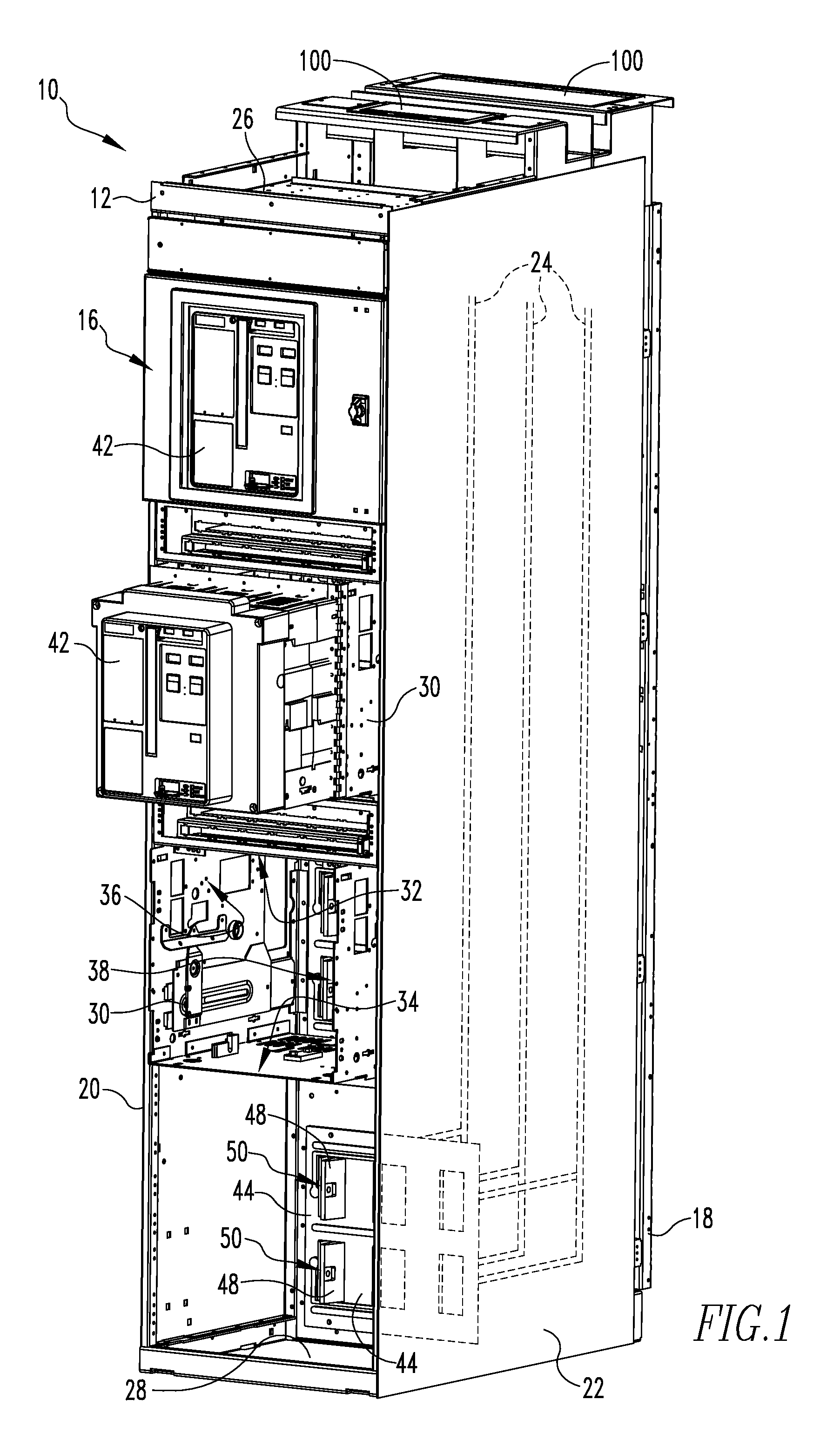
[0032]As employed herein, the term “circuit breaker” refers to an electrical circuit breaker that may be drawn into and out of an enclosure (e.g., without limitation, s...


PUM


Abstract

An electrical enclosure assembly is provided including a first enclosure and a second enclosure disposed within the first enclosure. The first enclosure having a plurality of walls defining an interior and an exterior with one of the walls including a first number of one way vents. The interior being substantially sealed from the exterior except at the first number of one way vents. The second enclosure having a plurality of walls defining an interior separate from the interior of the first enclosure. One of the plurality of walls of the second enclosure including a second number of one way vents. The interior of the second enclosure being substantially sealed from the interior of the first enclosure except at the second number of one way vents.

Description

BACKGROUND OF THE INVENTION[0001]1. Field of the Invention[0002]The invention relates generally to electric power distribution systems and, more particularly, to electrical enclosure assemblies for switchgear employed in such electric power distribution systems. The invention also relates to electrical enclosure assemblies for venting of gasses due to electrical arcing.[0003]2. Background Information[0004]Switchgear for electric power distribution systems includes electrical switching apparatus and their line and load terminations together with related equipment mounted in an electrical enclosure (typically a metal cabinet). Switchgear used in sections of electric power distribution systems operating at voltages up through 690 volts is classified as low voltage switchgear (according to international standards, although the ANSI standard for low voltage is a maximum of 600 volts). Typically, the electrical switching apparatus is a circuit breaker, but other switching apparatus such a...

Claims


Application Information

Patent Timeline
Patent Type & Authority Patents(United States)
IPC IPC(8): H02B1/26H05K7/20
CPCH02B13/025
Inventor COOMER, JARROD L.ABRAHAMSEN, MICHAEL H.METCALF, DAVID A.FAIR, TIMOTHY
Owner EATON INTELLIGENT POWER LTD
Why Eureka
Try Eureka