
Coaxial economizer assembly and method

a technology of economizer and assembly method, which is applied in the direction of refrigeration components, mechanical equipment, lighting and heating equipment, etc., can solve the problems of high reliability of centrifugal chillers, low maintenance requirements, and significant energy resources of centrifugal chillers in commercial and other high cooling and/or heating demand facilities

Active Publication Date: 2011-07-12
TRANE INT INC
View PDF139 Cites 18 Cited by
  • Summary
  • Abstract
  • Description
  • Claims
  • Application Information

AI Technical Summary

Benefits of technology

[0012]Embodiments of the coaxial economizer eliminates the traditional in-line design, combines multiple functions into one integrated system, improves fluid mixing of the inter-cooled gas prior to entry of the second stage and improves fluid flow dynamics (e.g. swirl reduction) through the system, which, in turn, improves chiller performance. The coaxial economizer is operable over a wide capacity range, and provides improved efficiency in a compact size.

Problems solved by technology

Typically, the reliability of centrifugal chillers is high, and the maintenance requirements are low.
Centrifugal chillers consume significant energy resources in commercial and other high cooling and / or heating demand facilities.
Prior chiller designs also typically connect the first stage discharge of a compressor to a second stage compressor and include complicated casting and piping arrangements.
In practice, the mixing of the two flows is not as thorough as desired and predominately occurs far enough down the fluid flow path, e.g. in the impellers of the second stage, that only a modest efficiency improvement is gained.

Method used


Image

  • Coaxial economizer assembly and method
  • Coaxial economizer assembly and method
  • Coaxial economizer assembly and method

Examples


Embodiment Construction

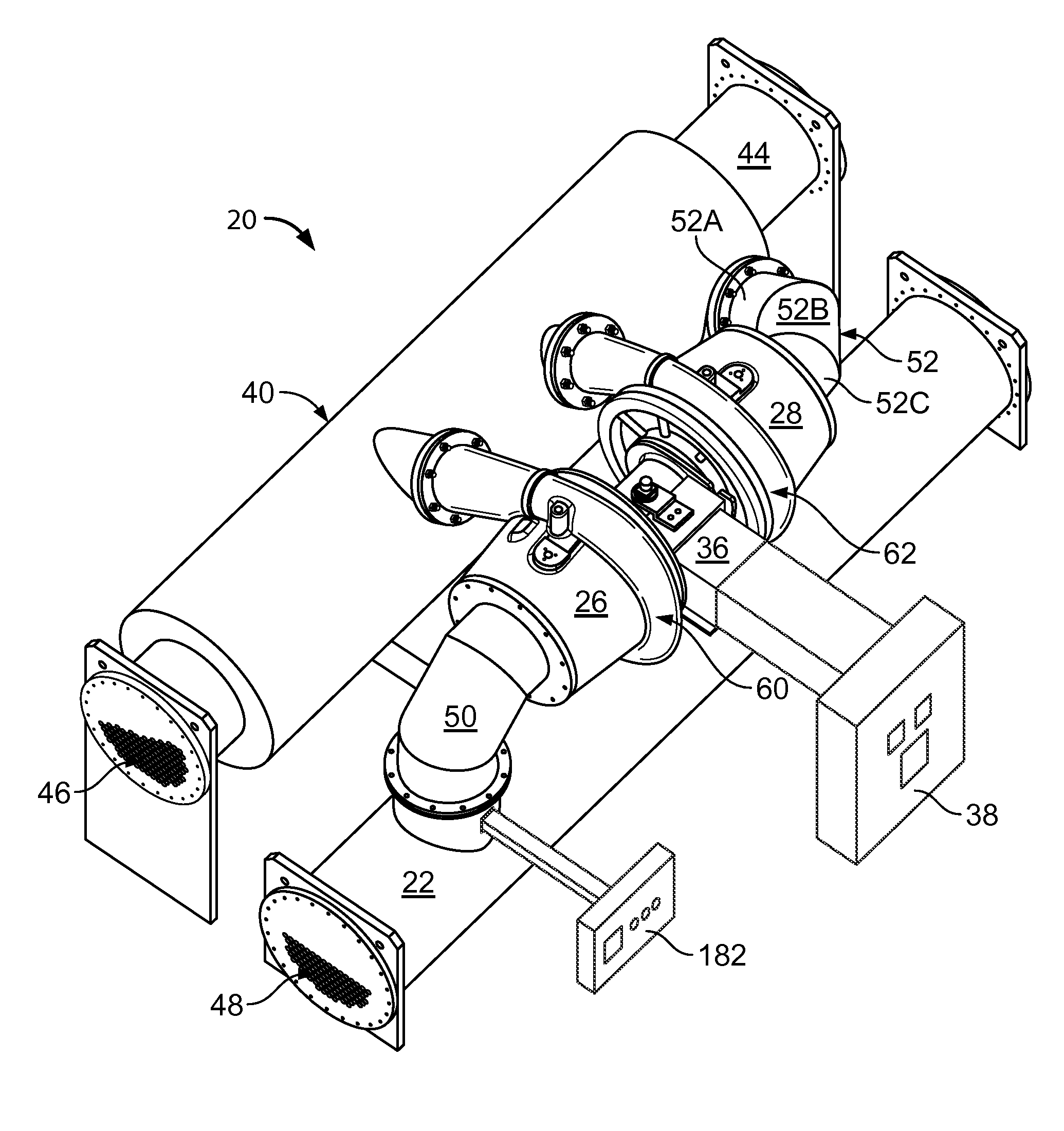
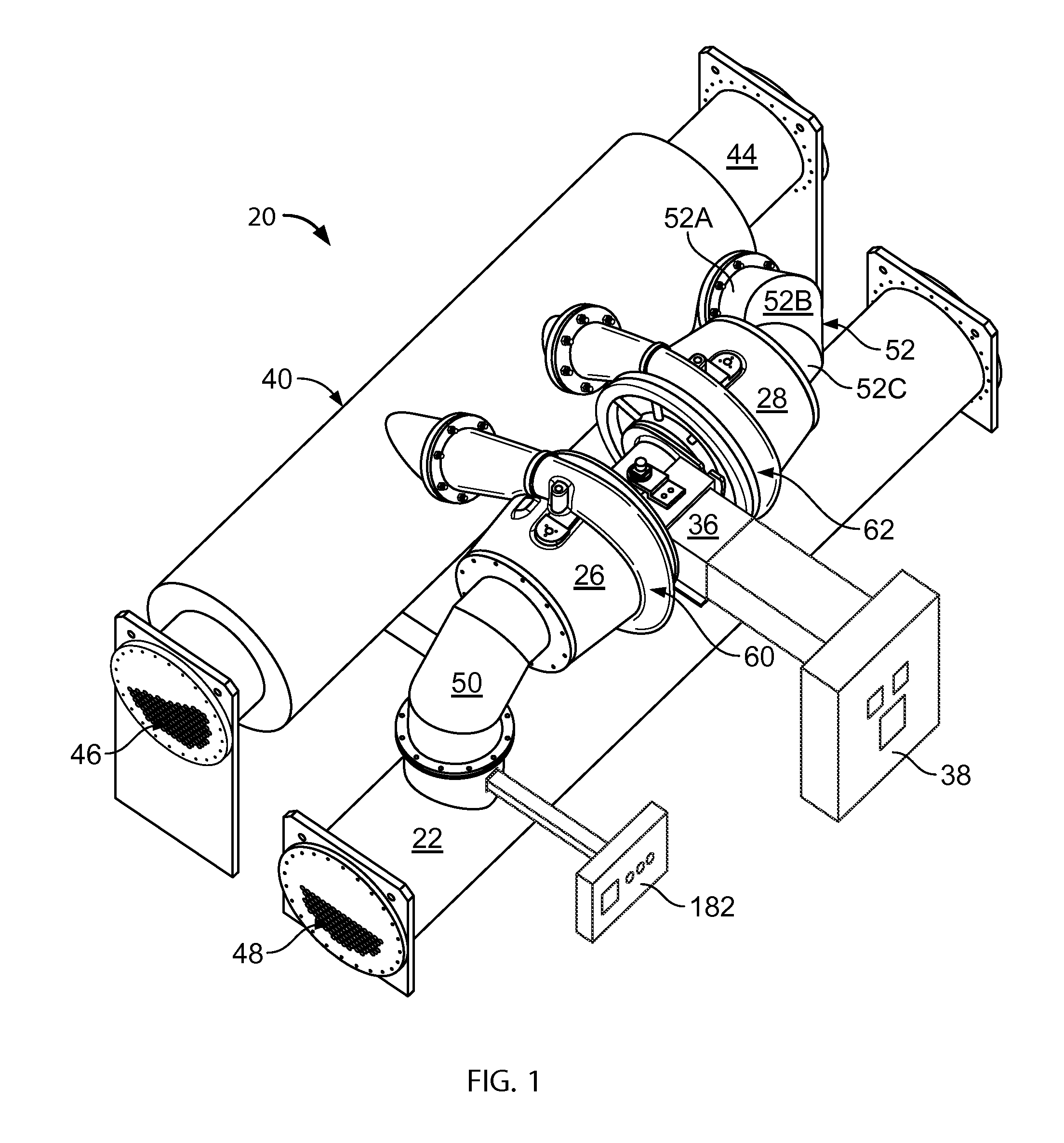
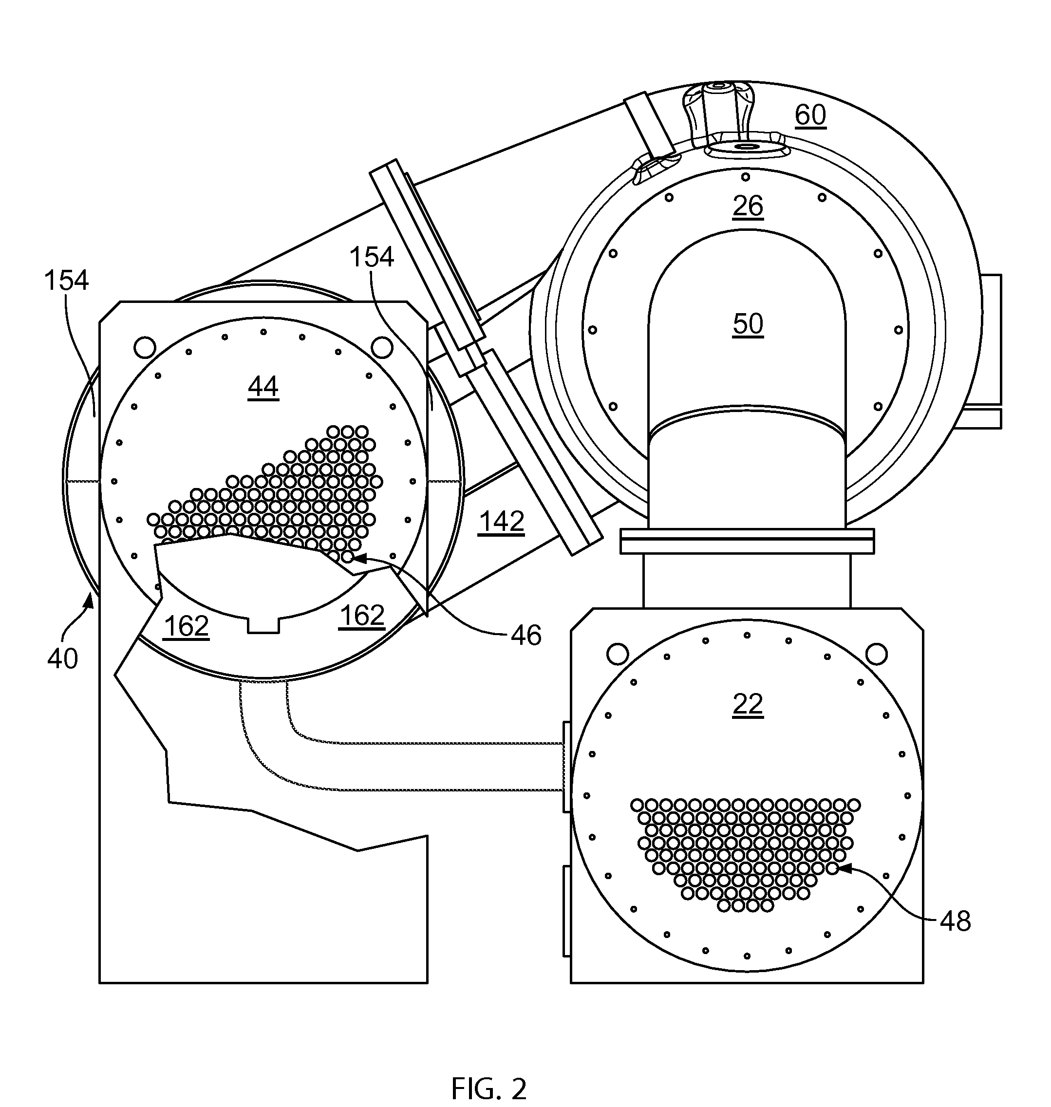
[0021]Referring to FIGS. 1-3 of the drawings, a chiller or chiller system 20 for a refrigeration system. A single centrifugal chiller system and the basic components of chiller 20 are illustrated in FIGS. 1-3. The chiller 20 includes many other conventional features not depicted for simplicity of the drawings. In addition, as a preface to the detailed description, it should be noted that, as used in this specification and the appended claims, the singular forms “a,”“an,” and “the” include plural referents, unless the context clearly dictates otherwise.

[0022]In the embodiment depicted, chiller 20 is comprised of an evaporator 22, multi-stage compressor 24 having a non-final stage compressor 26 and a final stage compressor 28 driven by a variable speed, direct drive permanent magnet motor 36, and a coaxial economizer 40 with a condenser 44. The chiller 20 is directed to relatively large tonnage centrifugal chillers in the range of about 250 to 2000 tons or larger.

[0023]In a preferred ...


PUM


Abstract

A coaxial economizer for use in a chiller system comprising an inner housing and an outer housing having a common longitudinal axis. The outer housing has an inlet for receiving a fluid from a upstream compressor stage of a multistage compressor and an outlet for conveying a fluid to a downstream compressor stage of a multistage compressor. A flow chamber forms a fluid flow path about the inner housing. A flash chamber is coterminous with the flow chamber and flashes fluid in a liquid state to a gas state. A flow passage between said flash chamber and the flow chamber for conveying a flashed gas from the flash chamber to the flow chamber; wherein the flashed gas conveyed from the flash chamber and the fluid received from the inlet of the outer housing mix along the fluid flow path toward the outlet of the outer housing.

Description

BACKGROUND OF THE INVENTION[0001]The present invention generally relates to an economizer for flash cooling a refrigerant liquid, and specifically with an economizer arranged coaxially with a condenser or other structure, e.g. an evaporator, for use in a refrigeration system having at least two stages of compression.[0002]Refrigeration systems typically incorporate a refrigeration loop to provide chilled water for cooling a designated building space. A typical refrigeration loop includes a compressor to compress refrigerant gas, a condenser to condense the compressed refrigerant to a liquid, and an evaporator that utilizes the liquid refrigerant to cool water. The chilled water is then piped to the space to be cooled.[0003]One such refrigeration or air conditioning system uses at least one centrifugal compressor and is referred to as a centrifugal chiller. Centrifugal compression involves the purely rotational motion of only a few mechanical parts. A single centrifugal compressor ch...

Claims


Application Information

Patent Timeline
Patent Type & Authority Patents(United States)
IPC IPC(8): F25B1/10
CPCF25B43/00F25B1/06F25B1/053F25B1/10F25B31/026F25B2400/13F25B2400/16F25B2500/18F25B2341/0662F25B41/39
Inventor JAMES, RICK T.HALEY, PAUL F.JANSSEN, RANDALL L.PLZAK, WILLIAM J.
Owner TRANE INT INC
Learn More