Detector array for use in a laser imaging apparatus

Inactive Publication Date: 2011-07-12
IMAGING DIAGNOSTIC SYST
View PDF25 Cites 0 Cited by
  • Summary
  • Abstract
  • Description
  • Claims
  • Application Information

AI Technical Summary

Benefits of technology

[0019]In summary, the present invention provides a detector array for use in a laser imaging apparatus, comprising a plurality of housings disposed in an arc around an opening in which an object to be scanned is disposed, each housing including an open front end, a rear end and a longitudinal axis; and a detector disposed within each housing at a distance from the front end, thereby to restrict the field of view of each detector. The housings are adapted to be orbited around the object about an orbit axis. Each detector is adapted to simultaneously detect light exiting from the object within the respective field of view of each detector. Each housing may be provided with a lens at its front end to further restrict the field of view of the detector.

Problems solved by technology

Cancer of the breast is a major cause of death among the American female population.
The x-ray absorption density resolution of present photographic x-ray methods is insufficient to provide reliable early detection of malignant tumors.
Tumors of this size rarely produce sufficient contrast in a mammogram to be detectable.
For these reasons, photographic mammography has been relatively ineffective in the detection of this condition.
Most mammographic apparatus in use today in clinics and hospitals require breast compression techniques which are uncomfortable at best and in many cases painful to the patient.
In addition, x-rays constitute ionizing radiation which injects a further risk factor into the use of mammographic techniques as most universally employed.
Light photon propagation is not straight-line and techniques to produce cross-sectional images are mathematically intensive.
The photon beam attenuation induced by the breast tissue reduces the available photon flux to an extremely low level and requires sophisticated techniques to capture the low level signals.
Methods to acquire the scanning data are engineering issues that acquire low level signals, simultaneous data acquisition from a large number of sensors surrounding the breast, multiple levels of sensors surrounding the breast to allow rapid data acquisition, and both rotation and translation control of sensors and laser beam.

Method used


Image

  • Detector array for use in a laser imaging apparatus
  • Detector array for use in a laser imaging apparatus
  • Detector array for use in a laser imaging apparatus

Examples


Embodiment Construction

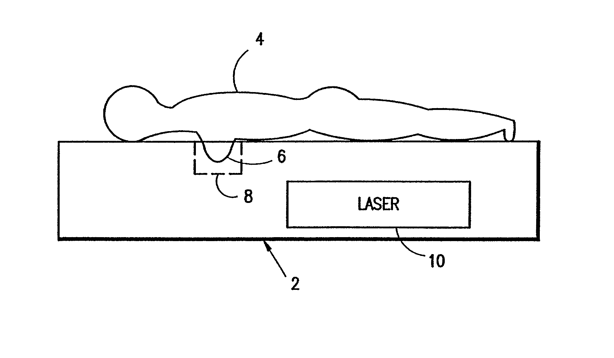
[0034]A scanning apparatus 2, such as that described in copending application Ser. No. 08 / 484,904, filed Jun. 7, 1995, now U.S. Pat. No. 5,692,511, is schematically disclosed in FIG. 1. A patient 4 is positioned prone on a top surface of the apparatus 2 with her breast 6 pendent within a scanning chamber 8. A laser beam from a laser source 10 is operably associated with the scanning chamber 8 to illuminate the breast 6.

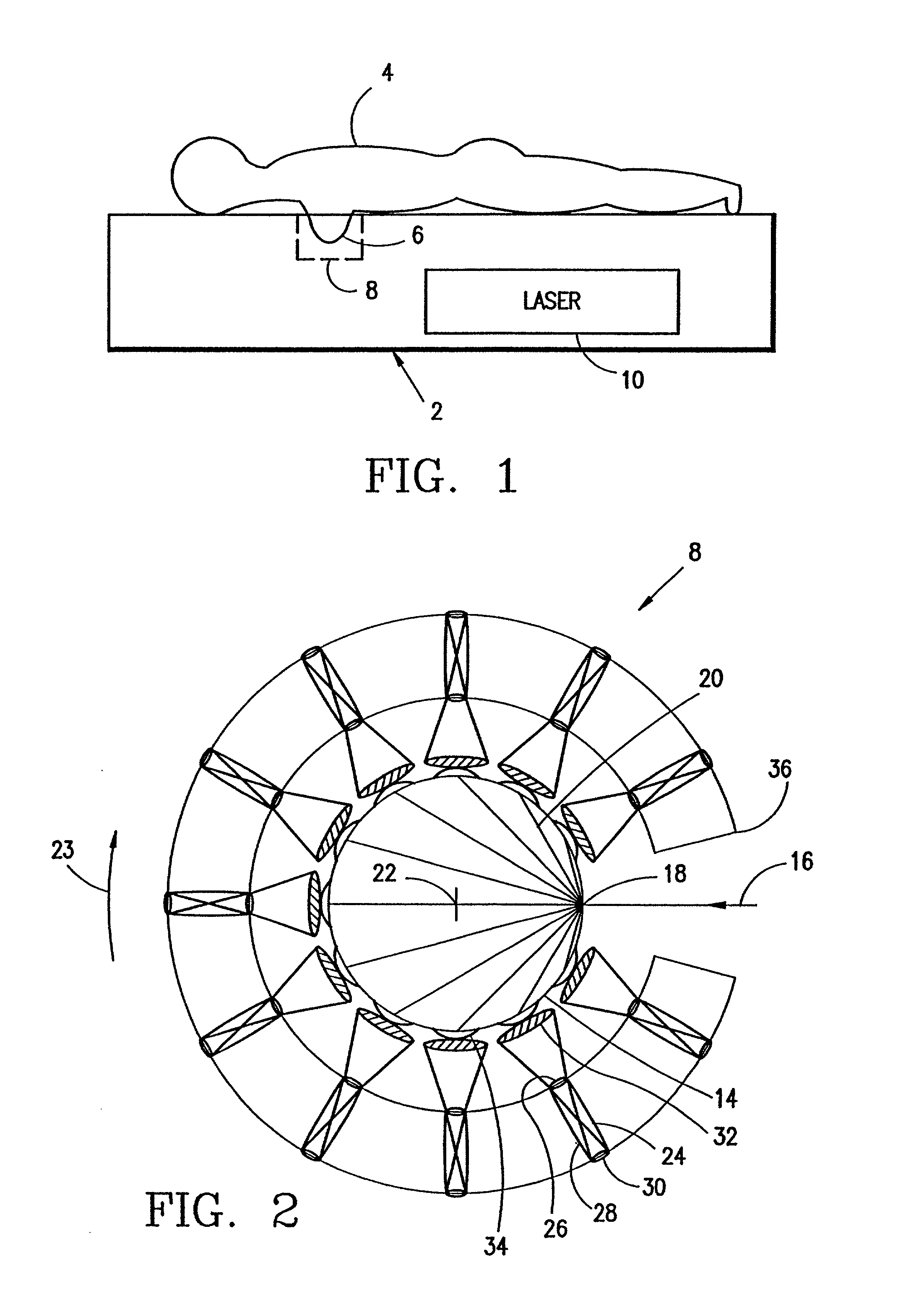
[0035]The scanning chamber 8 is shown schematically in plan view in FIG. 2. The scanning chamber includes a plurality of detector assemblies 12 disposed in an arc to define an opening in which an object 14 to be scanned is positioned. A laser beam 16 impinges the object at point 18. Light exiting from the object 18, such as the rays 20 is picked up by the respective detector assembly 12, which is then used to provide an image of the scanned object. The rays 20 are represented as chords originating from the point of entry 18 of the laser beam 16 and exiting at various ...


PUM


Abstract

A detector array for use in a laser imaging apparatus, comprises a plurality of housings disposed in an arc around an opening in which an object to be scanned is disposed, each housing including an open front end, a rear end and a longitudinal axis; and a detector disposed within each housing at a distance from the front end, thereby to restrict the field of view of each detector. The housings are adapted to be orbited around the object about an orbit axis. Each detector is adapted to simultaneously detect light exiting from the object within the respective field of view of each detector. A method for collecting light exiting from a object being scanned with a light source is also disclosed.

Description

RELATED APPLICATIONS[0001]This is a division of application Ser. No. 09 / 627,148, filed Jul. 27, 2000, now U.S. Pat. No. 6,211,512, which is a division of application Ser. No. 08 / 963,760, filed Nov. 4, 1997, now U.S. Pat. No. 6,100,520, which is a nonprovisional application claiming the benefits of provisional application Nos. 60 / 032,591, 60 / 032,592 and 60 / 032,593, all filed Nov. 29, 1996, all of which are hereby incorporated by reference.[0002]This application is related to provisional applications Ser. Nos. 60 / 032,591, 60 / 032,592 and 60 / 032,593, all filed on Nov. 29, 1996, which are hereby incorporated by reference.[0003]This application is also related to copending application Ser. No. 08 / 484,904, filed Jun. 7, 1995, which is hereby incorporated by reference.FIELD OF THE INVENTION[0004]The present invention relates generally to a diagnostic medical imaging apparatus that employs a near-infrared laser as a radiation source and a detector array with restricted fields of views direct...

Claims


Application Information

Patent Timeline
IPC IPC(8): A61B10/00H01J3/14A61B5/00
CPCA61B5/0091A61B5/4312A61B5/0073
Inventor WAKE, ROBERT H.GRABLE, RICHARD J.
Owner IMAGING DIAGNOSTIC SYST
Why Eureka
Try Eureka