Dispensing closure having a flow conduit with key-hole shape

a flow conduit and dispensing closure technology, applied in the field of squeeze-type container dispensing closures, can solve the problems of more difficult manufacturing, more expensive than traditional one-piece dispensing closures, and a messy appearan

Active Publication Date: 2011-07-19
WESTROCK SLATERSVILLE
View PDF76 Cites 12 Cited by
  • Summary
  • Abstract
  • Description
  • Claims
  • Application Information

AI Technical Summary

Benefits of technology

[0010]The present invention preserves the advantages of existing dispensing closures while providing new advantages not found in currently available dispensing closures and overcoming many disadvantages of such currently available dispensing closures. The general concept of the present invention is to provide a non-linear flow path from an interior of the dispensing closure to an exterior of the dispensing closure so that the product does not immediately spurt out upon opening of the closure lid and / or inverting and shaking the container to move the product toward the dispensing orifice.
[0012]A flow conduit extends through the upper deck for the passage of a viscous product, such as mustard. The flow conduit includes an entry orifice (inside the container) having an entrance axis and an exit orifice (outside the container) having an exit axis. The entrance axis is parallel to, but not co-linear with the exit axis to provide a non-linear flow path from the interior of the closure to the exterior of the closure. The bottom wall of the flow conduit thus prevents the direct flow of product into the flow conduit along the exit axis.
[0013]In another embodiment, the flow conduit defines a double key-hole shape. The flow conduit includes two entry orifices (inside the container) having different entrance axes and an exit orifice (outside the container) having an exit axis. The entrance axes are parallel to, but not co-linear with the exit axis to provide a non-linear flow path from the interior of the closure to the exterior of the closure. The bottom wall of the flow conduit thus prevents the direct flow of product into the flow conduit along the exit axis.
[0014]In another embodiment, the bottom wall is connected, attached, or integrally formed with the sidewall and front and back walls of the flow conduit. The bottom wall defines a flap, such as a key-hole flap, connected or attached to the side wall integrally formed with the upper deck, exit orifice, or spout. The bottom wall is molded vertically or downwardly and then pivoted or folded horizontally or upwardly to prevent the direct flow of product along the exit axis and through the exit orifice.
[0015]It is therefore an object of the present invention to provide a one-piece low cost dispensing closure that does not include a valve structure.
[0019]Another object of the embodiment is to provide a flow conduit that allows product to flow freely upon squeezing while also providing a passive flow restriction.

Problems solved by technology

Past dispensing closures tended to leak product onto the top deck of the closure after dispensing, creating a messy appearance and often requiring cleaning to reseal the closure.
While these silicone valves have been widely accepted by both the manufacturers and the consumers, they are somewhat more difficult to manufacture, as they require several inter-fitting parts, and thus they tend to be more expensive than traditional one-piece dispensing closures.
Another perceived drawback to the silicone valve closure is that they are constructed out of two different types of plastic and thus, from a recycling standpoint, they are more difficult to recycle because the silicone valve must be separated from the plastic closure body for recycling.
While this is not a major issue in the United States, at least yet, it is currently a major issue in Europe where recycling is extremely important and even mandated in some countries.
While the concept of the design may provide the desired flow characteristics, the design is virtually impossible to mold using conventional injection molding or blow molding techniques and thus is not commercially feasible.
While the circuitous path of this design is effective for water, the flow characteristics of water are different than other viscous fluids and thus the design is not believed to be suited for other more viscous products.
In short, it would be difficult to force viscous fluids through the multi-chamber design.

Method used


Image

  • Dispensing closure having a flow conduit with key-hole shape
  • Dispensing closure having a flow conduit with key-hole shape
  • Dispensing closure having a flow conduit with key-hole shape

Examples


Embodiment Construction

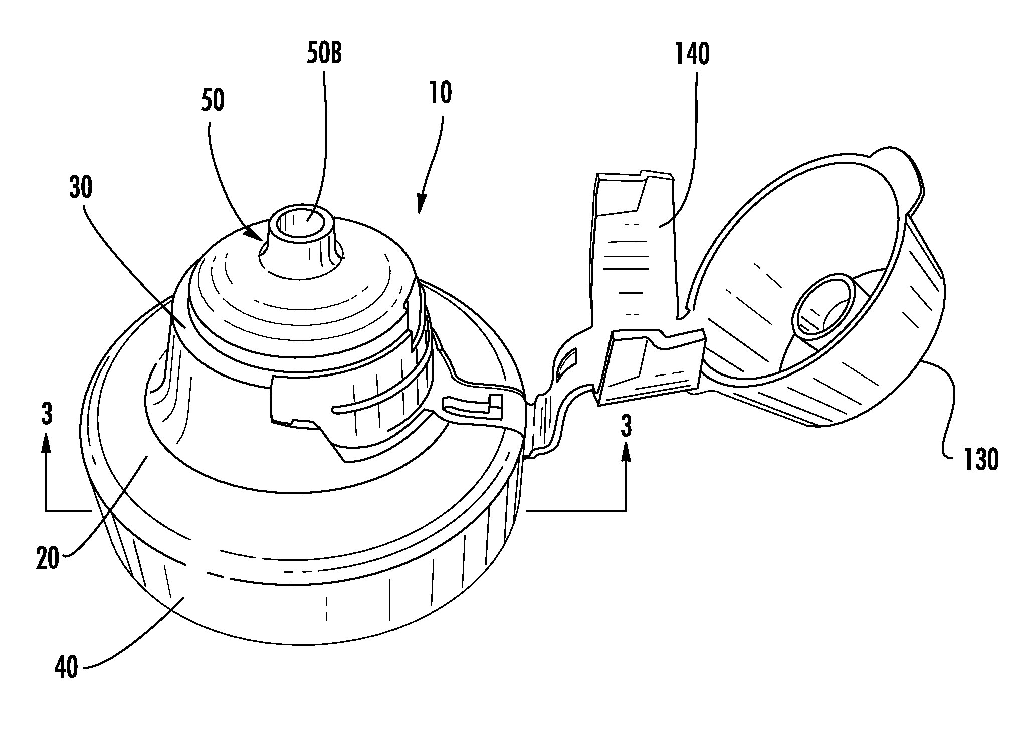
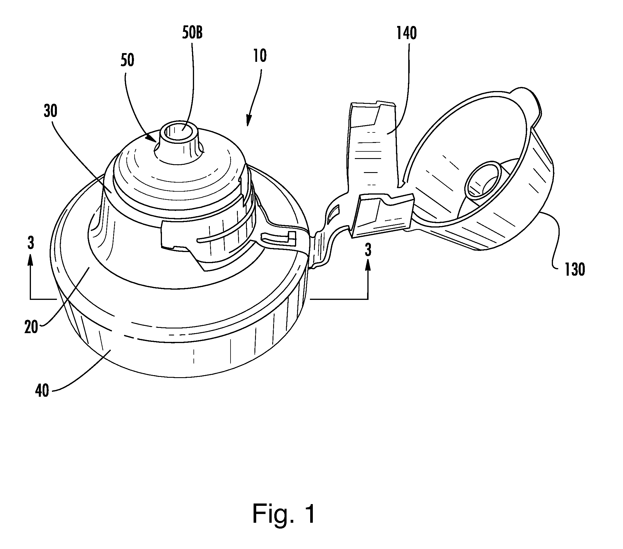
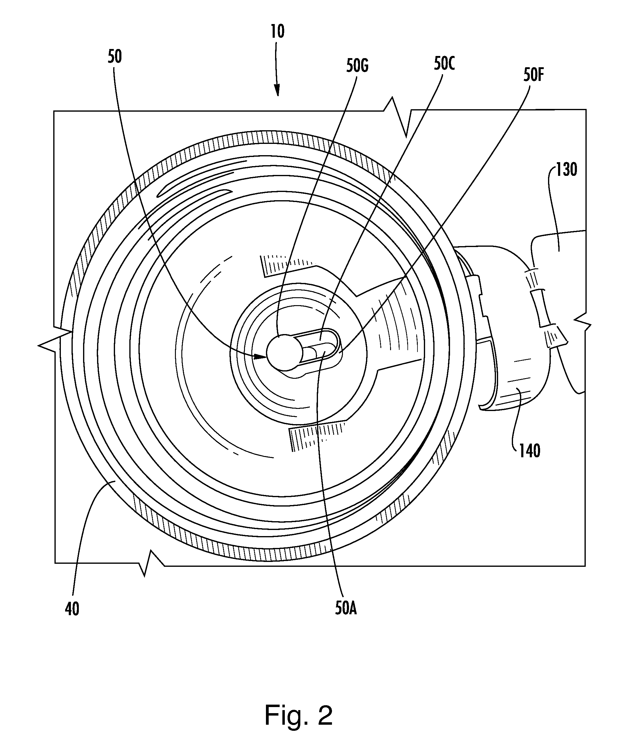
[0033]Referring now to the drawings, the dispensing closure 10 of the instant invention is illustrated in FIGS. 1-4. As will hereinafter be more fully described, the instant dispensing closure 10 includes a unique flow conduit arrangement, which includes an offset, obstructed, and non-linear flow path. The unique arrangement provides anti-spurting in upright containers as well as “suck-back” for cleaner product dispensing, i.e. “clean pour”.

[0034]Generally, the dispensing closure 10 comprises a closure body 20, a closure lid 130 and a living hinge structure 140 hingeably connecting the closure lid 130 to the closure body 20. The closure body 20 has an upper deck 30 and a skirt 40 depending from the upper deck 30 where the skirt 40 is configured and arranged to mount to a product container (not shown). Preferably, the product container is a conventional squeeze-type container. Preferably, the skirt 40 is internally threaded for threaded mounting on a product container (See FIG. 2). H...


PUM


Abstract

A dispensing closure has a key-hole shaped flow conduit that provides a sufficient flow restriction to prevent unwanted spurting of the product when the container is initially opened. The dispensing closure includes a closure body with an upper and lower deck, inner and outer skirt, and a flow conduit extending through the upper deck. The outer skirt is configured to mount to a product container. The flow conduit includes including two or more vertically oriented walls and a bottom wall. The bottom wall configured and arranged to be positioned along a horizontal axis. The flow conduit includes one or more entrance orifices having one or more entrance axes and an exit orifice having an exit axis. The entrance axis is stepped or offset from the exit axis whereby the flow conduit provides a non-linear flow path of product from an interior of the closure to an exterior of the closure.

Description

CROSS REFERENCE TO RELATED APPLICATIONS[0001]This continuation-in-part application is related to and claims priority from earlier filed, U.S. Non-Provisional patent application Ser. No. 11,849,979, filed Sep. 4, 2007, which is now U.S. Pat. No. 7,735,699, U.S. Provisional Patent Application No. 60 / 893,883 filed Mar. 8, 2007 and U.S. Provisional Patent Application No. 60 / 824,322 filed Sep. 1, 2006, all of which are incorporated herein by reference.BACKGROUND OF THE INVENTION[0002]The present invention relates to container closures, and more particularly to squeeze-type container dispensing closures.[0003]There are two major trends occurring in the design of dispensing containers and closures. The first trend is a focus on providing a “clean pour” during dispensing of the product. Many food products, such as mustard and ketchup, have a high viscosity and require the user to tip the container, shake down the product and then squeeze the container to dispense the product. Past dispensin...

Claims


Application Information

Patent Timeline
Patent Type & Authority Patents(United States)
IPC IPC(8): B65D47/00B65D39/00B65D43/18
CPCB65D47/06B65D47/0842B65D2547/063
Inventor BRANNON, PATRICK J.SKILLIN, CLIFFORD W.ROMANOV, SERGEY
Owner WESTROCK SLATERSVILLE
Why Eureka
Try Eureka