
Bucket type jaw crusher

a crusher and jaw technology, applied in the direction of roads, grain treatment, roads, etc., can solve the problems of increased labor and downtime, weak crushing power, and difficult crushing into fines, and achieve quick and easy replacement, easy lubrication of toggle plates, and strong crushing into fines.

Active Publication Date: 2011-07-19
UEDA IND
View PDF11 Cites 7 Cited by
  • Summary
  • Abstract
  • Description
  • Claims
  • Application Information

AI Technical Summary

Benefits of technology

[0010]An objective of the invention is to provide a bucket type jaw crusher which can perform strong crushing into fines within a short time. Another objective of the invention is to provide a bucket type jaw crusher which allows quick and easy replacement of the load receiving sections of the toggle plate and easy lubrication of the toggle plate.
[0011]In addition, another objective of the invention is to provide a bucket type jaw crusher which improves gripping and grinding of crushed objects and requires only one spare teeth plate. In addition, another objective of the invention is to provide a bucket type jaw crusher which can quickly respond to changes in the tension rod inclination while movable jaw teeth are in operation.
[0012]In addition, another objective of the invention is to provide a bucket type jaw crusher which can quickly remove crushed objects clogging the space between movable jaw teeth and stationary jaw teeth. Furthermore, another objective of the invention is to provide a bucket type jaw crusher which provides a counterweight between a hydraulic motor and a flywheel to improve the crushing speed.

Problems solved by technology

Conventionally in this kind of jaw crusher, a toggle plate supporting movable jaw teeth is installed with a state inclined downward toward its tip relative to the movable jaw teeth, and because the movable jaw teeth reciprocates in the direction of lifting the toggle plate at the time of crushing, there is the deficiency that crushing power is weak and crushing into fines is difficult.
In addition, the load receiving sections on the top and bottom of the toggle plate supporting the reciprocating motion of the movable jaw teeth wear out rapidly, the number of replacing them is large depending on the frequency of their use, and the jaw crusher needs to be disassembled and reassembled in order to perform replacement of those load receiving sections, with the deficiency that there is an increase in labor and downtime.
Because the load faces on the top and bottom of the toggle plate must be constantly lubricated with a lubricating oil, an oil pump needs to be installed, with the deficiency that piping and maintenance require some labor.
While as the teeth plate of conventional stationary jaw teeth, one having a vertically linear shape is used, and as the teeth plate of movable jaw teeth, one having a vertically linear shape or a gentle arc shape is used, if the stationary jaw teeth and movable jaw teeth are arranged in a V shape, there are such shortcomings as a large gripping angle, poor crushing performance, and the necessity of separate spare teeth plates.
Because the conventional toggle plate supports the bottom of movable jaw teeth in a state inclined downward toward its tip, even if a bucket is inverted to remove clogging of crushed objects, the toggle plate hinders securing enough space between the movable jaw teeth and the stationary jaw teeth, with the deficiency that the clogging of crushed objects could not be fully resolved.

Method used


Image

  • Bucket type jaw crusher
  • Bucket type jaw crusher
  • Bucket type jaw crusher

Examples


embodiment 1

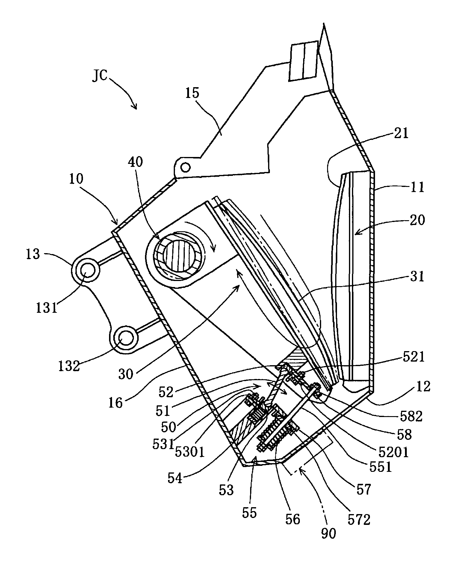
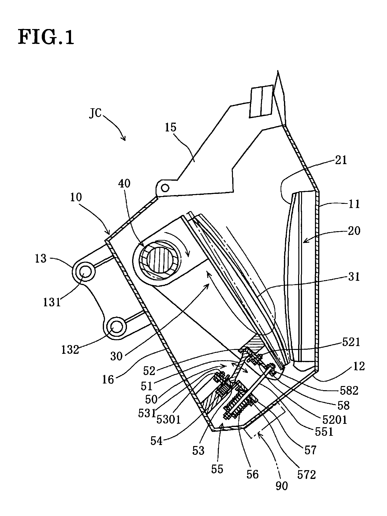
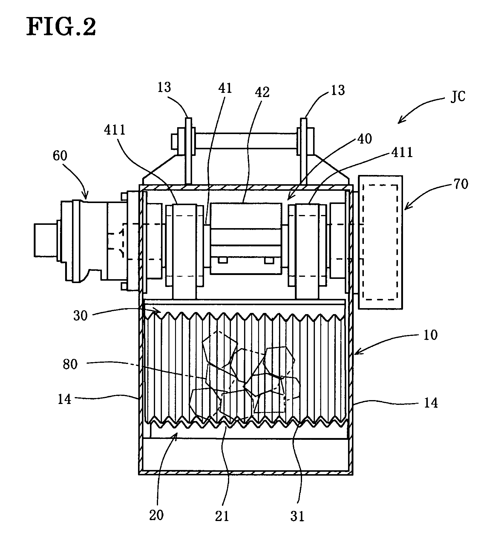
[0039]A bucket type jaw crusher JC of embodiment 1 is explained based on FIG. 1˜FIG. 9. As shown in FIG. 1, the bucket type jaw crusher JC comprises a stationary jaw teeth 20, a movable jaw teeth 30, an eccentric main shaft 40, a toggle plate mechanism 50, and an electromagnet 90, and crushes an object to be crushed 80 by pressing it onto the stationary jaw teeth 30 with the movable jaw teeth 20 through the rocking motion of a toggle plate 51.

[0040]The stationary jaw teeth 20 comprises wavy teeth 21 with a plurality of mountains and valleys formed vertically in a gentle arc shape on the inner surface side and are fixed to the inner face of the bottom section 11 of bucket 10. The movable jaw teeth 30 has wavy teeth 31 with a plurality of mountains and valleys formed vertically in a gentle arc shape so as to engage with the wavy teeth 21 of the stationary jaw teeth 20 on the inner surface side. The wavy teeth 21 of the stationary jaw teeth 20 and the wavy teeth 31 of the movable jaw t...

embodiment 2

[0059]A bucket type jaw crusher JCB is explained based on FIG. 10˜FIG. 13. Since the same reference numerals are assigned to the same components as in Embodiment 1, the explanation thereof is omitted.

[0060]As shown in FIG. 11 and FIG. 12, the bucket type jaw crusher JCB comprises a stationary jaw teeth 20B, a movable jaw teeth 30B, an eccentric main shaft 40B, a toggle plate unit 50B, and an electromagnet 90B. Because the constitution of the stationary jaw teeth 20, the movable jaw teeth 30B, the eccentric main shaft 40B, and the electromagnet 90B are the same as in Embodiment 1 of the present invention, the detailed explanation is omitted.

[0061]The toggle plate unit 50B comprises a toggle plate 51B, a movable jaw teeth side load receiving section 52B, a bucket side load receiving section 53B, and a tension rod 551B. Because the constitutions of the toggle plate 51B, the upper load receiving section 52B, and the lower load receiving section 53B are the same as in Embodiment 1, their...


PUM


Abstract

A bucket type jaw crusher comprises a hydraulic motor connected to one end of an eccentric main shaft, a flywheel connected to the other end of the eccentric main shaft, and a counterweight for balance adjustment fitted at an intermediate section of the eccentric main shaft between the hydraulic motor and the flywheel. A movable jaw teeth side load receiving section of a toggle plate is placed at an upper position than a bucket side load receiving section of the toggle plate, and while movable jaw teeth are reciprocated by rotation of the eccentric shaft, an object to be crushed is pressed against stationary jaw teeth by the movable jaw teeth via rocking motion of the toggle plate.

Description

BACKGROUND OF THE INVENTION[0001]The present invention relates to a bucket type jaw crusher for processing waste materials such as waste concrete, waste building material, and waste pavement material.[0002]Conventionally in this kind of jaw crusher, as shown in FIG. 1 of Patent Document 1, a toggle plate 30 supporting movable jaw teeth 20 is installed with a state inclined downward toward its tip relative to the movable jaw teeth, and the movable jaw teeth reciprocates in the direction of lifting the toggle plate at the time of crushing. At this time, the reciprocating motion of the movable jaw teeth is supported by load receiving sections 21 on the upper and lower portions of the toggle plate. Because lubricating oil must be constantly supplied to lubricate the upper and lower load faces of the toggle plate, an oil pump is installed.[0003]As the teeth plate of stationary jaw teeth, one having a vertically linear shape is used. As the teeth plate of movable jaw teeth, one having a v...

Claims


Application Information

Patent Timeline
Patent Type & Authority Patents(United States)
IPC IPC(8): B02C1/06
CPCB02C1/04E01C19/05E02F9/2267E02F3/965E02F3/404
Inventor UEDA, TOSHIHARU
Owner UEDA IND
Learn More