Method for manufacturing piezoelectric actuator, method for manufacturing liquid transporting apparatus, piezoelectric actuator, and liquid transporting apparatus

a piezoelectric actuator and actuator technology, applied in piezoelectric/electrostrictive/magnetostrictive devices, piezoelectric/electrostriction/magnetostriction machines, printing, etc., can solve problems such as proportions being susceptible to damage, and achieve the effect of relieving stress concentration and suppressing damag

Active Publication Date: 2011-07-19
BROTHER KOGYO KK
View PDF14 Cites 4 Cited by
  • Summary
  • Abstract
  • Description
  • Claims
  • Application Information

AI Technical Summary

Benefits of technology

[0009]An object of the present invention is to provide a method for manufacturing piezoelectric actuator which is capable of suppressing occurrence of damage such as breaking and cracking of the ceramics material layer, by relieving the stress concentration in the stacked body at the time of joining the stacked body of the ceramics material layers upon sintering, to a substrate.

Problems solved by technology

Moreover, when the stacked body of the ceramics material layers is joined to a substrate by pressing against the substrate after the stacked body is sintered, a stress is concentrated in a portion of the stacked body (particularly, a portion facing an edge portion of a deformation receiving area, in other words, a boundary between the deformation receiving area and a constrained area), and this portion is susceptible to damage.

Method used


Image

  • Method for manufacturing piezoelectric actuator, method for manufacturing liquid transporting apparatus, piezoelectric actuator, and liquid transporting apparatus
  • Method for manufacturing piezoelectric actuator, method for manufacturing liquid transporting apparatus, piezoelectric actuator, and liquid transporting apparatus
  • Method for manufacturing piezoelectric actuator, method for manufacturing liquid transporting apparatus, piezoelectric actuator, and liquid transporting apparatus

Examples


first modified embodiment

[0093]In the method of manufacturing the ink-jet head of the embodiment, the individual electrodes 32 are formed on the upper surface of the piezoelectric layer 30 after the through holes 45 are formed in the resin layer 41 on the upper side after joining the stacked body 40 having the both side covered by the resin layers 41 and 42 respectively, to the channel unit 4 (refer to FIG. 6A to FIG. 6E). However, the stacked body 40 may be formed on the channel unit 4 after carrying out the through hole forming step of forming the through holes 45 in the resin layer 41, and the electrode forming step of forming the individual electrodes 32 inside the through holes 45.

[0094]Concretely, the through holes 45 are formed by the laser machining (through hole forming step) in an area of the resin layer 41 on the upper side, which faces the pressure chambers 14 when the stacked body 40 is joined to the channel unit 4 as shown in FIG. 11C, after a sintering step in FIG. 11A, and a resin layer form...

second modified embodiment

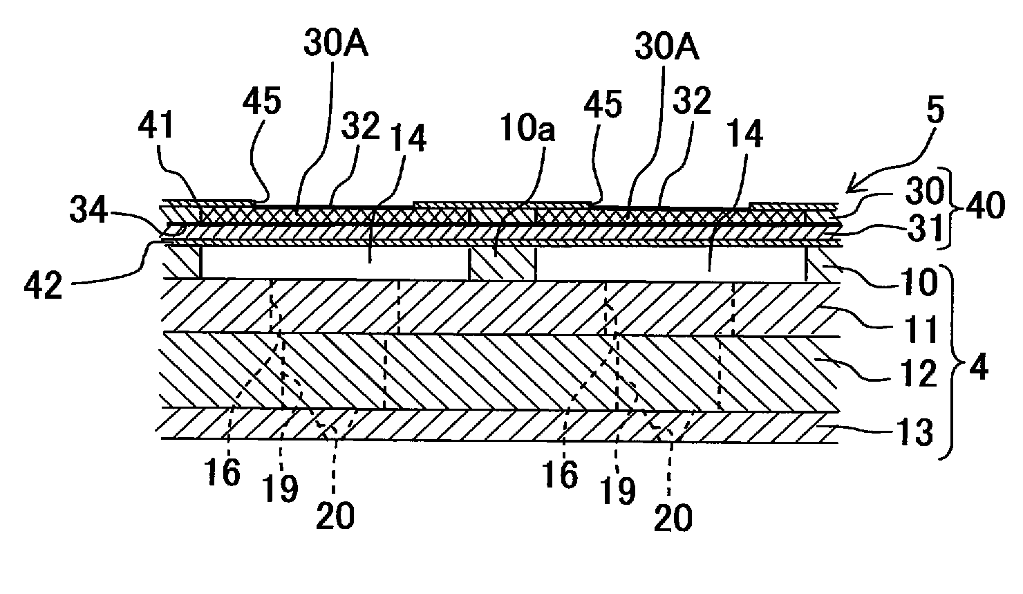
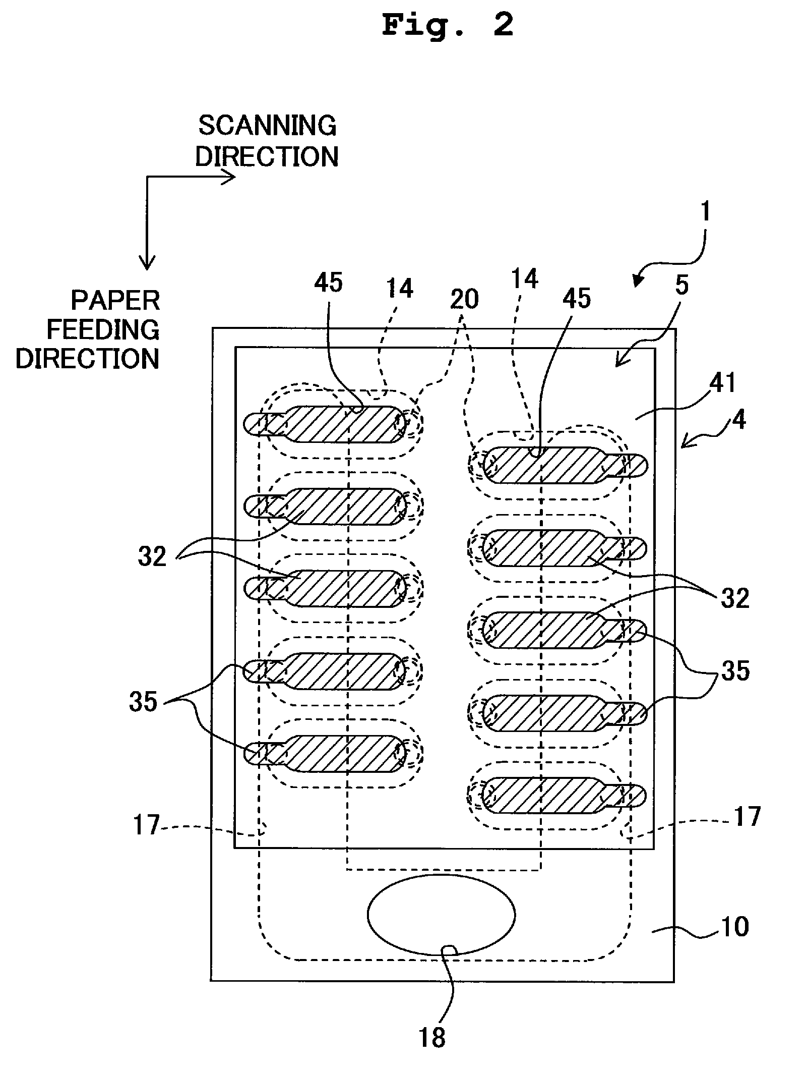
[0096]As shown in FIG. 12 and FIG. 13, the contact points 35 for connecting the individual electrodes 32 and the FPC are not particularly required to be arranged directly on the upper surface of the piezoelectric material layer 30 same as the individual electrodes 32, and the contact points 35 may be arranged on the surface of the resin layer 41 which covers the upper surface of the piezoelectric material layer 30.

[0097]In a structure of the second modified embodiment, the resin layer 41 is interposed between the contact points 35 and the upper surface of the piezoelectric material layer 30. Therefore, it is possible to suppress an unnecessary electrostatic capacitance from being generated between the common electrode 34 and the contact point 35 drawn from an individual electrode 32 when the driving electric potential is applied to that certain individual electrode 32. Moreover, since the contact points 35 which are to be connected to the FPC are at a position which is one stage hig...

third modified embodiment

[0100]The individual electrode is not necessarily required to be arranged in an area on the upper surface of the piezoelectric material layer, corresponding the central portion of the pressure chamber 14. For example, as shown in FIG. 15 and FIG. 16, after forming a through hole 45C having almost a ring shape, in an area of the resin layer covering the upper surface of the piezoelectric material layer 30, corresponding a peripheral portion of the pressure chamber 14, an individual electrode 32C having a ring shape may be formed in an inner-side area of the through hole 45C, and a contact point 35 which is drawn from the individual electrode 32C may be formed.

[0101]In a piezoelectric actuator of the third modified embodiment shown in FIG. 15 and FIG. 16, when the driving electric potential is applied to the individual electrode 32C, due to contraction of the piezoelectric material layer 30 in a horizontal direction, in a driving area corresponding the peripheral portion of the pressu...


PUM


Abstract

A method for manufacturing piezoelectric actuator which includes a piezoelectric layer formed of a piezoelectric ceramics material and having a drive area, a first electrode and a second electrode arranged on both surfaces of the piezoelectric material layer respectively each at portion corresponding to the drive area, and a ceramics layer formed of a ceramics material and stacked to face the surface of the piezoelectric material layer on which the first electrode is arranged, the method including: forming a stacked body which includes the piezoelectric material layer, the ceramics layer, and the first electrode, and sintering the stacked body; forming the second electrode on the other surface, of the piezoelectric material layer after the sintering, not facing the ceramics layer; and forming elastic layers having a lower coefficient of elasticity than that of the piezoelectric material layer on both surfaces respectively of the stacked body after the sintering.

Description

CROSS REFERENCE TO RELATED APPLICATION[0001]The present application claims priority from Japanese Patent Application No. 2007-091994, filed on Mar. 30, 2007, the disclosure of which is incorporated herein by reference in its entirety.BACKGROUND OF THE INVENTION[0002]1. Field of the Invention[0003]The present invention relates to a piezoelectric actuator which is used in an apparatus such as a liquid transporting apparatus.[0004]2. Description of the Related Art[0005]A piezoelectric actuator which drives an object by using a deformation (piezoelectric distortion) of a piezoelectric material layer when an electric field acts, has hitherto been known. For example, in Japanese Patent Application Laid-open No. 2006-181958 (FIG. 7), a piezoelectric actuator which is provided to an ink-jet head which jets an ink from nozzles has been described.[0006]The piezoelectric actuator described in Japanese Patent Application Laid-open No. 2006-181958 is an actuator which is arranged on one surface ...

Claims


Application Information

Patent Timeline
Patent Type & Authority Patents(United States)
IPC IPC(8): B41J2/045H01L41/00B41J2/055B41J2/135B41J2/14B41J2/16H01L41/083H01L41/09H01L41/187H01L41/22H01L41/257H01L41/313
CPCB41J2/161B41J2/1631B41J2/1632B41J2/1642B41J2/1645B41J2/1646H01L41/0474H01L41/25H01L41/293H01L41/0973H01L41/0833H01L41/273H10N30/2047H10N30/03H10N30/097H10N30/063H10N30/503H10N30/874H10N30/053
Inventor SUGAHARA, HIROTO
Owner BROTHER KOGYO KK
Why Eureka
Try Eureka