Profiled rail

a profiled rail and rail technology, applied in the field of profiled rails, can solve the problems of substantial increase in mounting costs, additional costs in order, and tilting of the profiled rail, and achieve the effects of reducing static values, facilitating mounting of the profiled rail, and improving flexural and torsional strength

Active Publication Date: 2011-07-26
HILTI AG
View PDF46 Cites 26 Cited by
  • Summary
  • Abstract
  • Description
  • Claims
  • Application Information

AI Technical Summary

Benefits of technology

[0012]In the inventive profiled rail, the opposite wall sections of the side walls form, during passing of the attachment element, a sidewise guide for the attachment element in the interior of the profiled rail. The sidewise guide insures passing of the attachment element without hooking or tilting. Further, the sidewise guide prevents tilting of the profiled rail that is mounted on a constructional component, when the profiled rail is loaded transverse to the profile axis. Advantageously, the minimal distance between the opposite wall sections of the side walls to each other is smaller than opening width of the openings measured in a direction perpendicular to the longitudinal profile axis.
[0014]Advantageously, at least the first through-opening or openings is (are) formed as an elongate opening(s). This makes possible adjustment of the profiled rail with respect to the inserted attachment element in direction of the grater opening width. Advantageously, both the first and second openings are formed as elongate openings, with the elongate openings advantageously being aligned in the same direction in which the longitudinal axis of the profiled rail extends.
[0015]Advantageously, there is provided a second connection wall spaced from the first connection wall for connecting the two side walls, with the first opening being formed in the first connection wall and the second opening being formed in the second connection wall. The connection walls and the side walls form together a circumferentially closed profile, so that the profiled rail has an advantageous flexural and torsional strength.
[0016]Advantageously, at least one of the openings has a collar extending into the interior of the profiled rail. The collar provides an additional sidewise guide for passing the attachment element through the profiled rail, further facilitating mounting of the profiled rail on a constructional component. The collar further compensates, at least partially, the reduction of static values caused by partial weakening of the corresponding connection wall due to the through-opening(s) formed therein. The collar is preferably formed by a drawn-through opening.
[0017]Advantageously, the collar has a section at least some portions of which abut an inner side of the side walls, providing support for the side walls. Thereby, the free effective length of the side walls is shortened. This is particular advantageous when the profiled rail is formed off a thin material and is subjected to a buckling and bending load.
[0019]Advantageously, the inventive profiled rail is formed of metal and, more advantageously of sheet metal by a stamping and bending process and / or a rolling process. This insures a simple and economical production of the inventive profiled rail.

Problems solved by technology

The drawback of the above-described rail consists in that during the insertion of the attachment element through one of the openings for securing the profiled rail, the attachment element can engage an edge of the opposite opening which substantially increases mounting costs, in particular, at an overhead mounting of a profiled rail on a ceiling that forms the structural component.
Therefore, in this case additional costs are required in order to prevent tilting of the profiled rail, which is spaced from the constructional component, in a direction transverse to the profile axis under a load.
The drawback of the rail of the Swiss publication consists in that with this rail, likewise during passing of the attachment element through the through-openings, it can engage the edge of the opposite through-opening.
Because the two opposite through-openings have different opening widths, there exists a danger that at mounting of the profiled rail at a distance from the constructional component, the profiled rail would tilt in a direction transverse to the profile axis under load unless expensive measures are undertaken to prevent tilting.

Method used


Image

  • Profiled rail
  • Profiled rail

Examples


Embodiment Construction

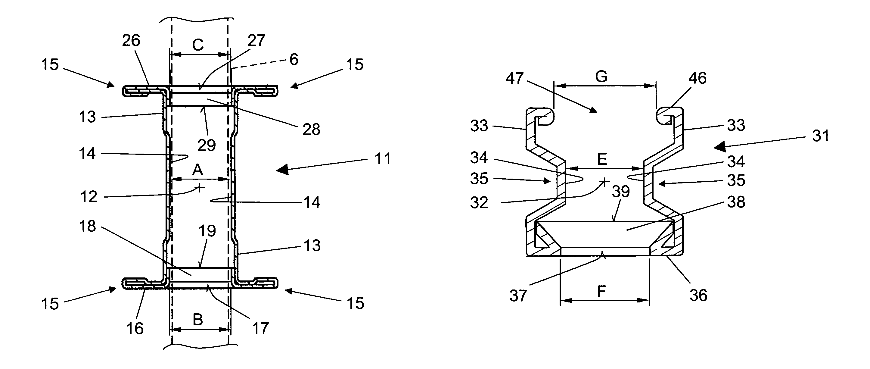
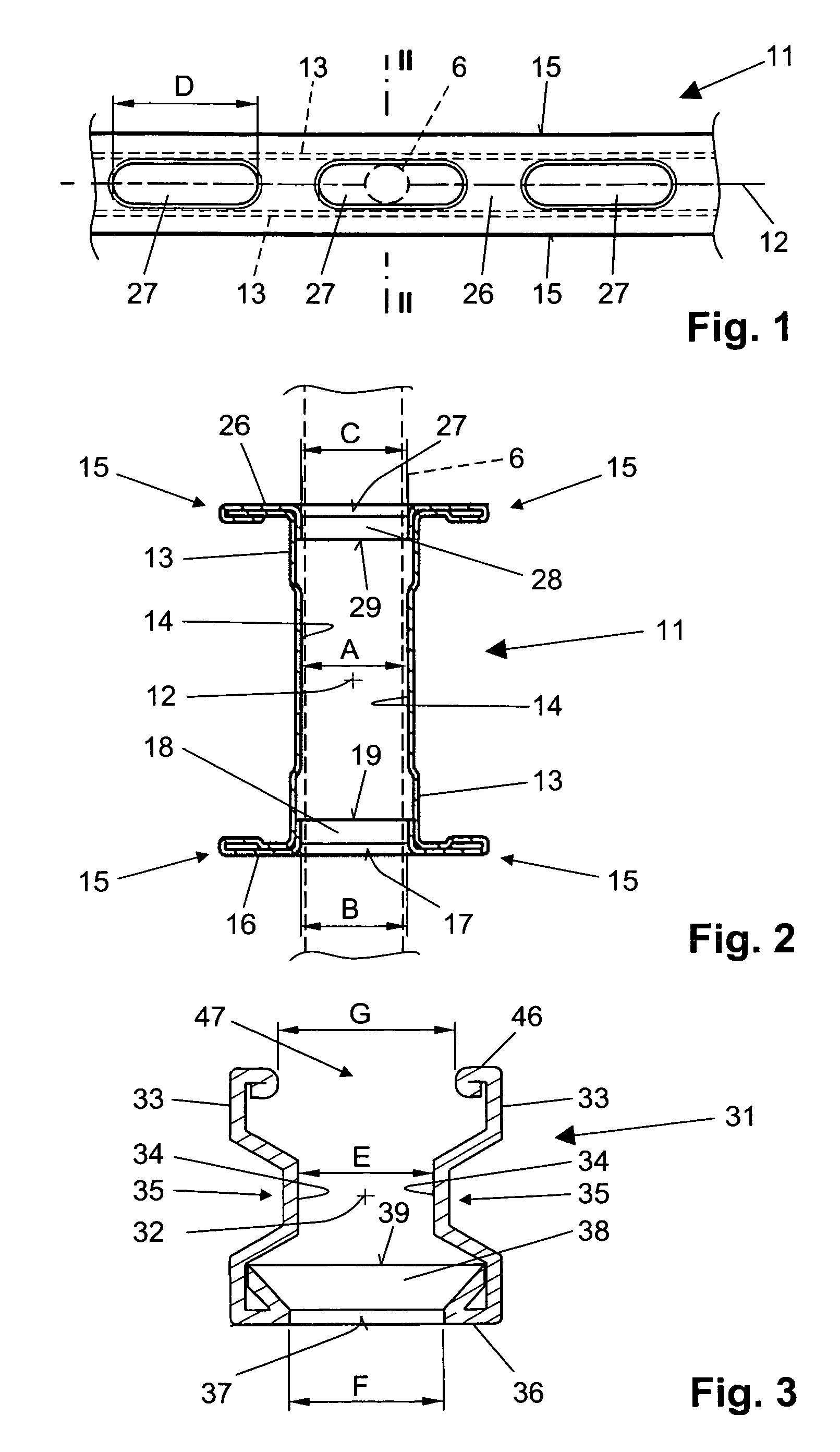
[0026]A profiled rail 11, which is shown in FIGS. 1-2, is formed of sheet metal and is designed for being suspended from a constructional component (not shown) with an attachment element 6. The profiled rail 11 has a longitudinal profile axis 12, two opposite side wall section 14, and two connection walls 16 and 26 connecting both side walls 13. The connection walls 16, 26 extend substantially perpendicular to planes in which the side walls 13 are located. Because of accumulation of material on edges 15 of the profiled rail 11, the profiled rail 11 even with reduced sheet metal thickness has an increased flexural and torsional strength in comparison with at least partially circumferentially closed profiled rail without accumulation of material on the edges.

[0027]In the first connection wall 16, there is provided a first through-opening 17 having an opening width B in a direction perpendicular to the longitudinal profile axis 12, and in the second connection wall 26, there is provide...


PUM


Abstract

A profiled rail has two opposite side walls (13) at least one connection wall (16) for connecting the side walls (13), first and second openings (17, 37; 27, 47) for passing therethrough a connection element (6) and having, respectively, first and second opening widths (B; F; C; G) measured in a direction perpendicular to a longitudinal profile axis (12) of the profiled rail, with a minimal distance (A; E) between the opposite wall sections (14; 34) of the side walls (13; 33), which is measured in the direction perpendicular to the longitudinal profile axis (12) of the profiled rail, at most corresponding to the opening width of (B; F; C; G) the first and second openings (17, 37; 27; 47).

Description

BACKGROUND OF THE INVENTION[0001]1. Field of the Invention[0002]The present invention relates to a profiled rail for being suspended from a constructional component and having two opposite side walls having opposite wall sections respectively, a first connection wall for connecting the two side walls with each other, and having a first opening for passing therethrough a connection element that secures the profiled rail on the constructional component, with the first opening having a first opening width measured in a direction perpendicular to a longitudinal profile axis of the profiled rail, and a second opening located opposite the first opening for passing through the connection element and having a second opening width measured in a direction perpendicular to a longitudinal profile axis of the profiled rail.[0003]2. Description of the Prior Art[0004]Profiled rails of the type described above are used for attachment of different installations such as tubular conduits, cable channe...

Claims


Application Information

Patent Timeline
Patent Type & Authority Patents(United States)
IPC IPC(8): E04C3/00E04C2/52E04H12/00
CPCE04C3/065E04C3/07E04C3/09H02G3/263E04C2003/0421E04C2003/0434E04C2003/0465E04C2003/0473
Inventor BIMBAUM, ULRICHMUNDWILER, LUKAS
Owner HILTI AG
Why Eureka
Try Eureka