Imaging apparatus and imaging method
a technology which is applied in the field of imaging apparatus and imaging method, can solve problems such as difficulty in obtaining the optimum light exposure condition group
- Summary
- Abstract
- Description
- Claims
- Application Information
AI Technical Summary
Problems solved by technology
Method used
Image
Examples
first embodiment
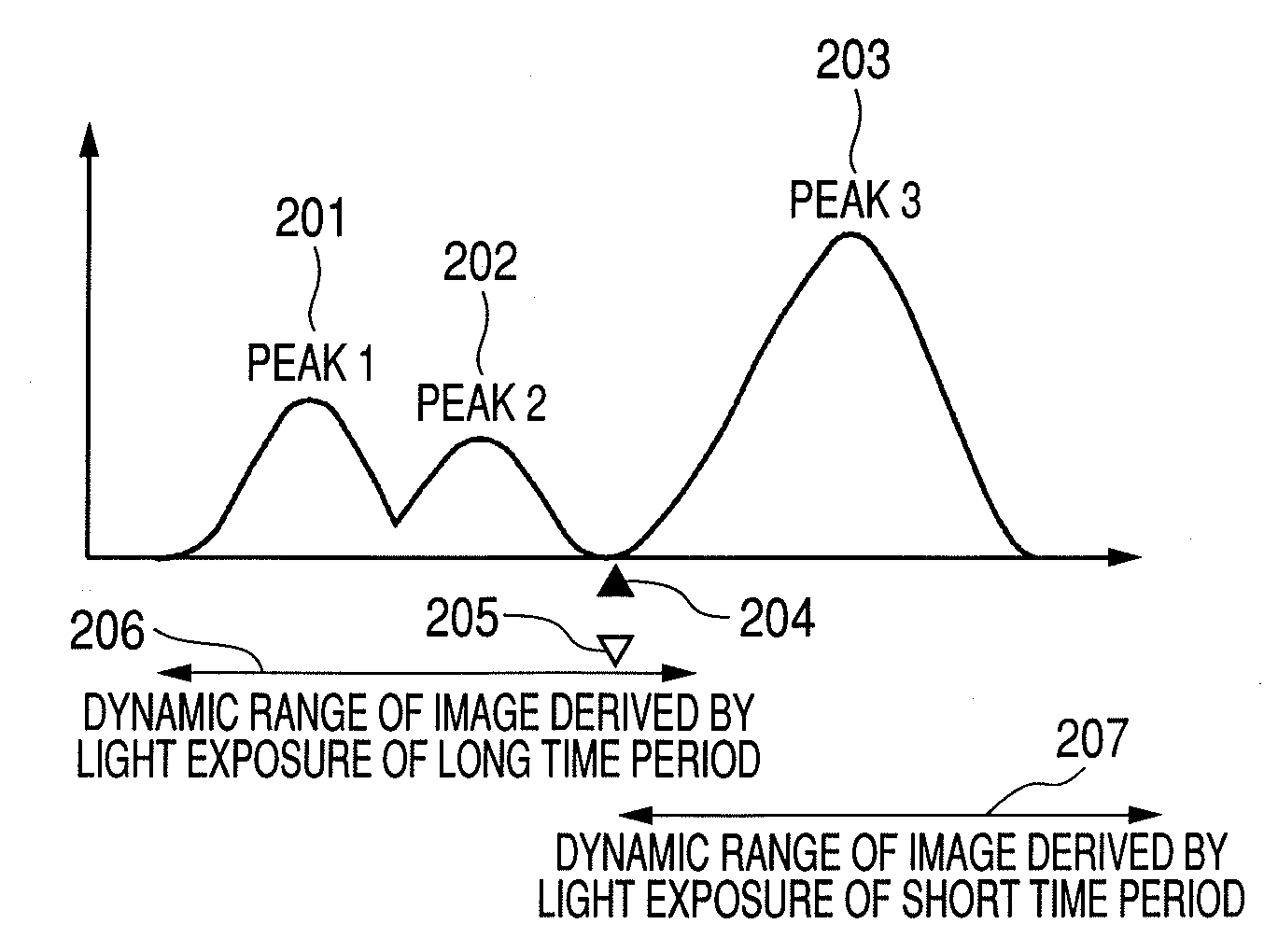
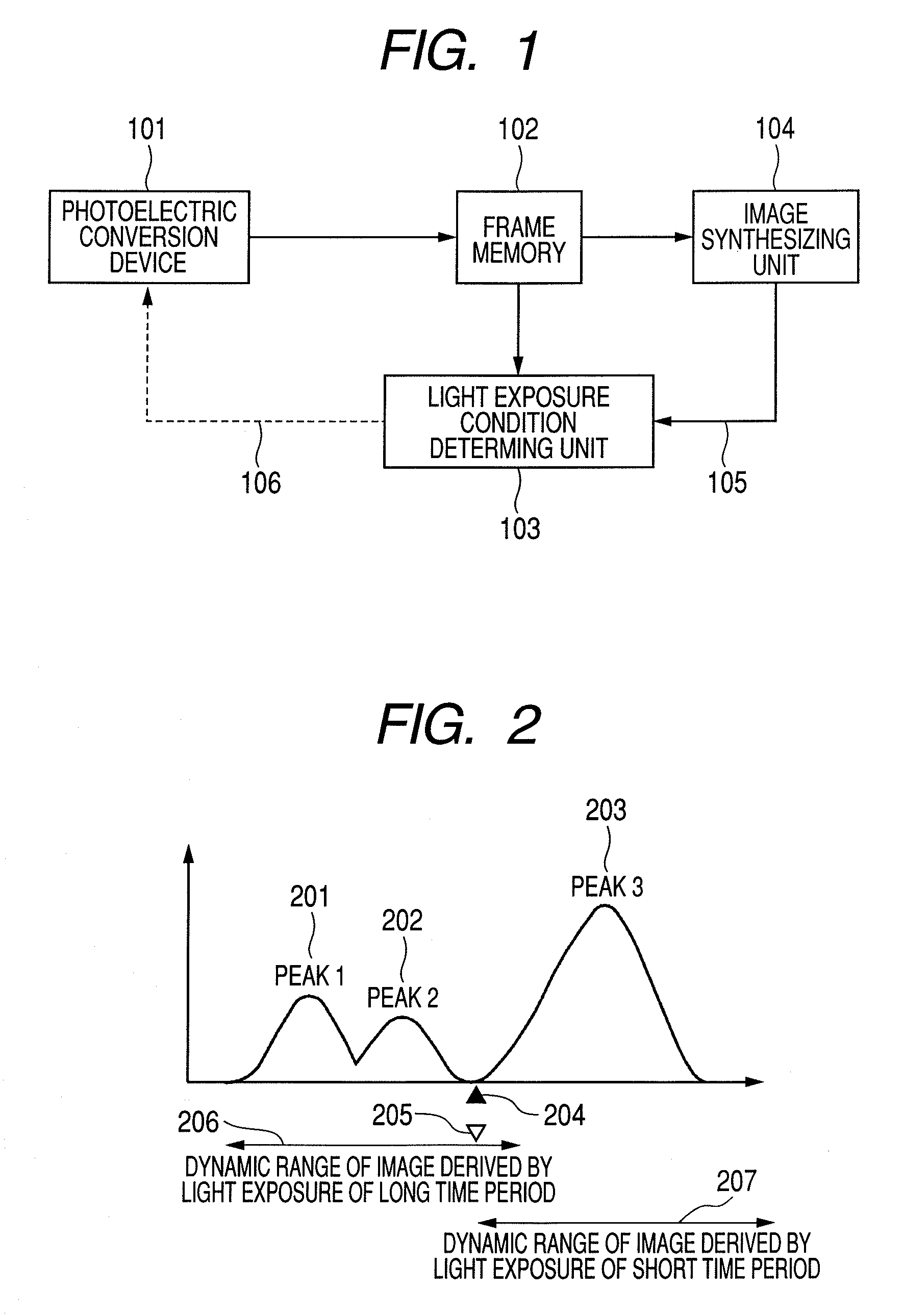
[0026]FIG. 1 is a block diagram illustrating an example of the configuration of a wide dynamic range imaging apparatus according to a first embodiment of the present invention. A photoelectric conversion device 101 converts optical information of an imaging scene to an electrical signal; specifically a CCD and a CMOS image sensor are cited for example. By photographing an imaging scene under a certain light exposure condition, the photoelectric conversion device 101 performs the operation of converting the range of the luminance of the imaging scene accommodated in its input dynamic range to an image signal. The image signal of an image output by the photoelectric conversion device 101 is temporarily accumulated in a frame memory 102 and thereafter is output to a light exposure condition determining unit 103 and an image synthesizing unit 104. The image synthesizing unit 104 generates a synthesized image signal from the image signals of a plurality of images of different light expos...
second embodiment
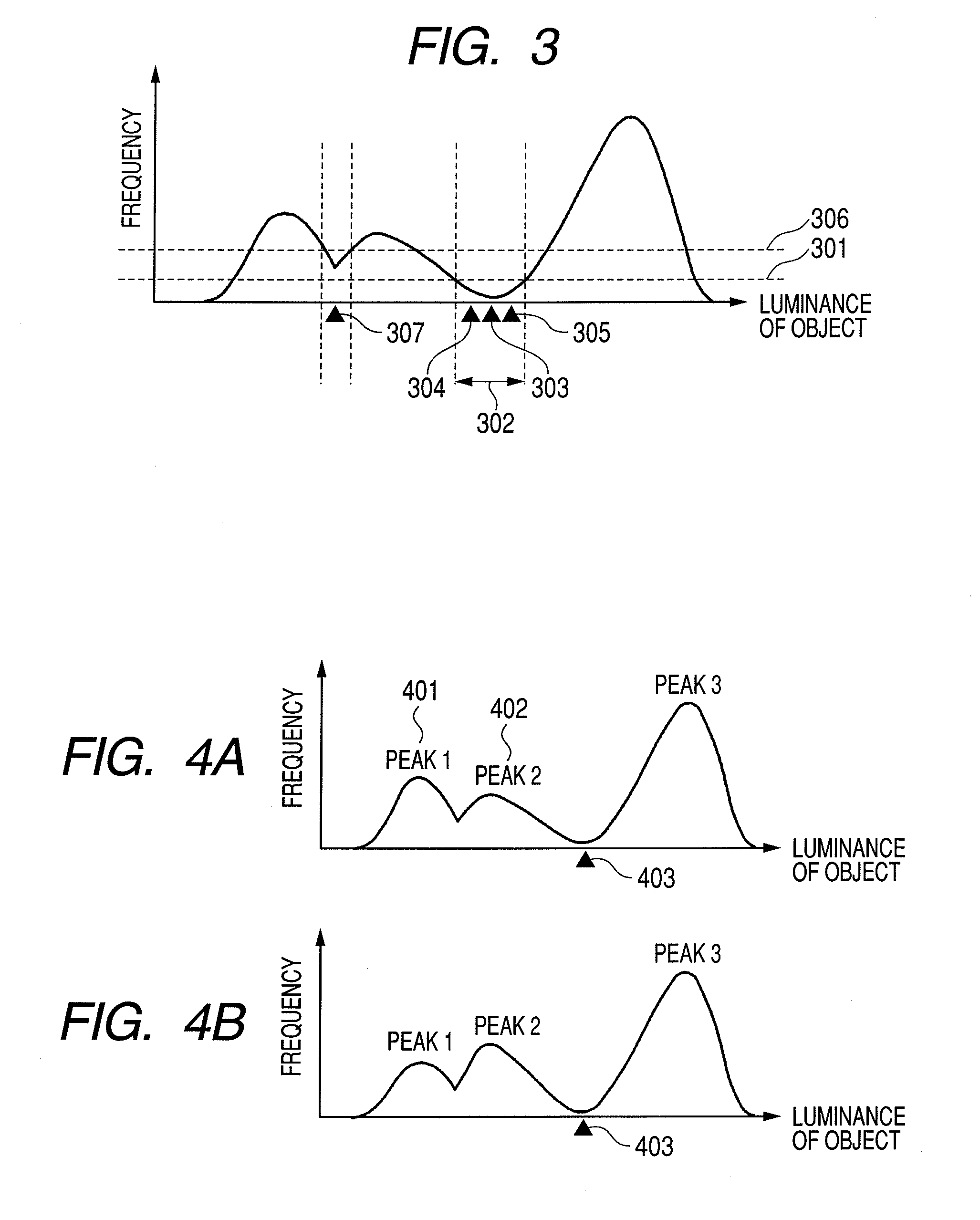
[0056]FIGS. 4A and 4B are views illustrating the imaging method of an imaging apparatus according to a second embodiment of the present invention. The present embodiment assumes that objects change their luminance with time, such as in the taking of moving pictures; for example, a scene is assumed in which the magnitude relation between the frequencies of peaks 401 and 402 changes frequently as illustrated in FIGS. 4A and 4B, due to a blinking light source or constantly varying sunlight appearing through trees.
[0057]By using the technique of the first embodiment, the light exposure condition group does not significantly change even when the peak positions of the histogram of the luminance distribution of an imaging scene replace each other as illustrated in FIGS. 4A and 4B, since the light exposure condition group is calculated using a value 403 belonging to the bottom of a ravine as the reference in the present embodiment.
[0058]An effect unique to the present embodiment will be des...
third embodiment
[0060]FIG. 5 is a view describing the imaging method of an imaging apparatus according to a third embodiment of the present invention. Here, a histogram having three peaks at spaced positions is assumed. The present embodiment has an imaging scene of a dynamic range of luminance much wider than those of the first and second embodiments; by a technique performing synthesis based on two images, the scene would have many pixels in the synthesized image suffering the white raise or black fall phenomenon.
[0061]The operation of the present embodiment in such a case will be described below. The configuration of the imaging apparatus is exactly the same as that of FIG. 1. First, in the same way as the first and second embodiments, a histogram of luminance of objects as shown in FIG. 5 is obtained based on some preceding photographing operation. The histogram obtained as a result of the preceding photographing operation is analyzed by the image synthesizing unit 104 to determine that a synth...
PUM
 Abstract
Description
Claims
Application Information
 - R&D
- Intellectual Property
- Life Sciences
- Materials
- Tech Scout
- Unparalleled Data Quality
- Higher Quality Content
- 60% Fewer Hallucinations
Browse by: Latest US Patents, China's latest patents, Technical Efficacy Thesaurus, Application Domain, Technology Topic, Popular Technical Reports.
© 2025 PatSnap. All rights reserved.Legal|Privacy policy|Modern Slavery Act Transparency Statement|Sitemap|About US| Contact US: help@patsnap.com


