Poynting-vector filter

a technology of a vector filter and a source of electromagnetic radiation, which is applied in the direction of digital variable/waveform display, instruments, measurement devices, etc., can solve the problems of buried signals, and it is difficult to pick out the contribution of a facility or electrical device/system (i.e., radiated signals) to a broadband data stream using just conventional filtering techniques

Inactive Publication Date: 2011-08-02
LAWRENCE LIVERMORE NAT SECURITY LLC
View PDF3 Cites 4 Cited by
  • Summary
  • Abstract
  • Description
  • Claims
  • Application Information

AI Technical Summary

Benefits of technology

[0008]Another object is to provide a novel signal filtering or tagging method that allows frequency components or content in the electromagnetic spectrum to be grouped or separated from the broadband spectrum according to the characteristic of having the same observed Poynting vector, which tends to indicate a common source, in the absence of detailed information about location, bearing or source characteristics.

Problems solved by technology

A major complication encountered in characterizing the electronic emissions of a facility or any other radiating electromagnetic source is that the signals of interest are often buried across the frequency spectrum of a noisy broadband record.
Unless it is fortuitously known exactly what to look for, it will be impossible to pick out a facility's or electrical device's / system's contributions (i.e., radiated signals) to a broadband data stream using just conventional filtering techniques.

Method used


Image

  • Poynting-vector filter
  • Poynting-vector filter
  • Poynting-vector filter

Examples


Embodiment Construction

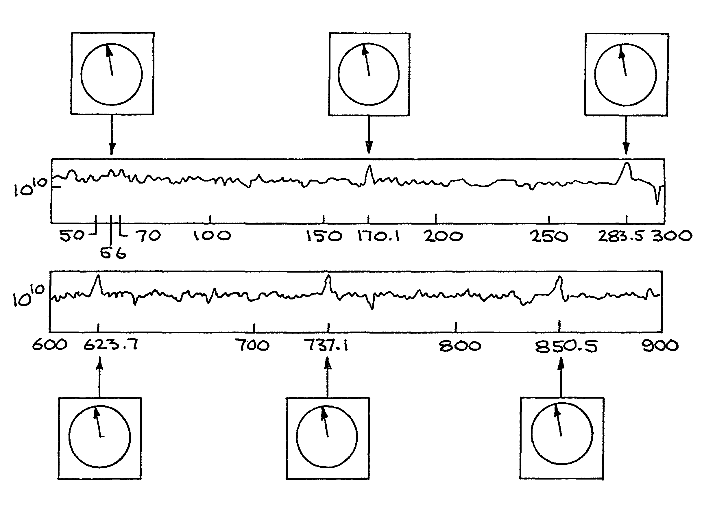
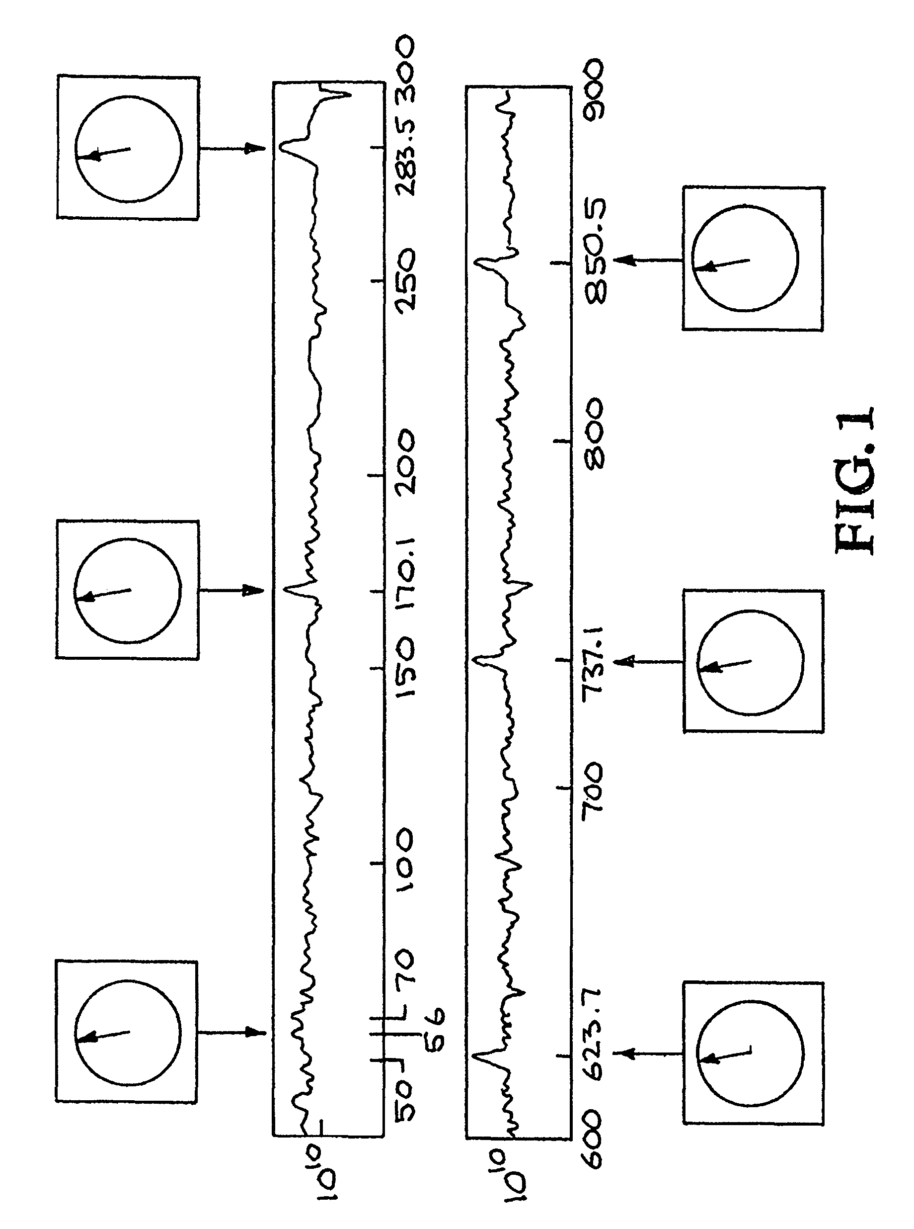
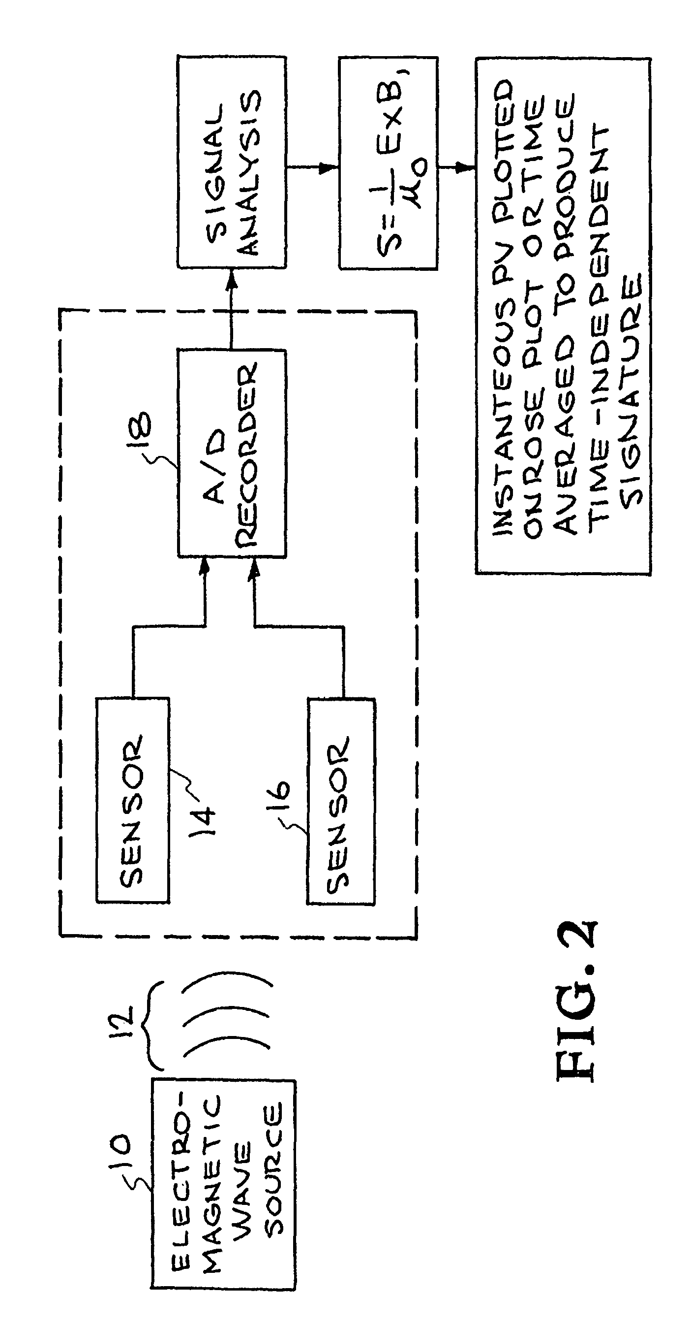
[0020]The invention is a method for providing the Poynting Vector “tag” for each harmonic or frequency component of a radiating electrical source / load system. This tag, which is unique to radiation from a particular location, corresponds to the bearing of a radiating electrical source / load system and is useful for facility / system monitoring and characterization purposes. For simplicity, the description given here involves a single set of sensors (one triaxial E and one triaxial B-field sensor) but can readily be extended to a network of sensors for detecting and tagging a variety of signal sources below and above the Earth's surface, in and on bodies of water as well as in the atmosphere and space.

[0021]FIG. 1 shows peaks in the power spectrum associated with harmonics of detected power / load system as well as virtually identical azimuthal Poynting vectors calculated for each harmonic. Poynting vectors calculated for other, unrelated peaks in the spectrum will be in different directi...


PUM


Abstract

A determination is made of frequency components associated with a particular bearing or location resulting from sources emitting electromagnetic-wave energy for which a Poynting-Vector can be defined. The broadband frequency components associated with a specific direction or location of interest are isolated from other components in the power spectrum that are not associated with the direction or location of interest. The collection of pointing vectors can be used to characterize the source.

Description

[0001]This is a continuation-in-part of U.S. patent application Ser. No. 11 / 404,609 (now U.S. Pat. No. 7,440,858) titled: “A POYNTING-VECTOR BASED METHOD FOR DETERMINING THE BEARING AND LOCATION OF ELECTROMAGNETIC SOURCES”, filed Apr. 13, 2006, incorporated herein by reference, which claims priority to U.S. Provisional Patent Application No. 60 / 671,793, filed Apr. 15, 2005, and incorporated by reference.[0002]The United States Government has rights in this invention pursuant to Contract No. DE-AC52-07NA27344 between the United States Department of Energy and Lawrence Livermore National Security, LLC.BACKGROUND OF THE INVENTION[0003]1. Field of the Invention[0004]The present invention relates to the methods for identifying the location of a source of electromagnetic radiation, and more specifically, it relates to the detection of unknown electromagnetic signals from broadband noise and the use of their Poynting vectors to identify the location of the signal source.[0005]2. Descriptio...

Claims


Application Information

Patent Timeline
Patent Type & Authority Patents(United States)
IPC IPC(8): G01R13/00
CPCG01R29/0892
Inventor CARRIGAN, CHARLES R.
Owner LAWRENCE LIVERMORE NAT SECURITY LLC
Why Eureka
Try Eureka