Correlation weighted reverse time migration imaging method based on wave field separation

A technology of reverse time migration imaging and wave field separation, which is applied in the direction of measuring devices, instruments, scientific instruments, etc., can solve the problems of low universality and too large human-influenced factors on the imaging section, and achieve high-precision imaging Effect

Active Publication Date: 2021-06-25
OCEAN UNIV OF CHINA
View PDF11 Cites 3 Cited by
  • Summary
  • Abstract
  • Description
  • Claims
  • Application Information

AI Technical Summary

Problems solved by technology

However, the conventional wave field separation method still has the following problems in the application process: for the various imaging profiles obtained after wave field separation, t...

Method used


Image

  • Correlation weighted reverse time migration imaging method based on wave field separation
  • Correlation weighted reverse time migration imaging method based on wave field separation
  • Correlation weighted reverse time migration imaging method based on wave field separation

Examples


Embodiment 1

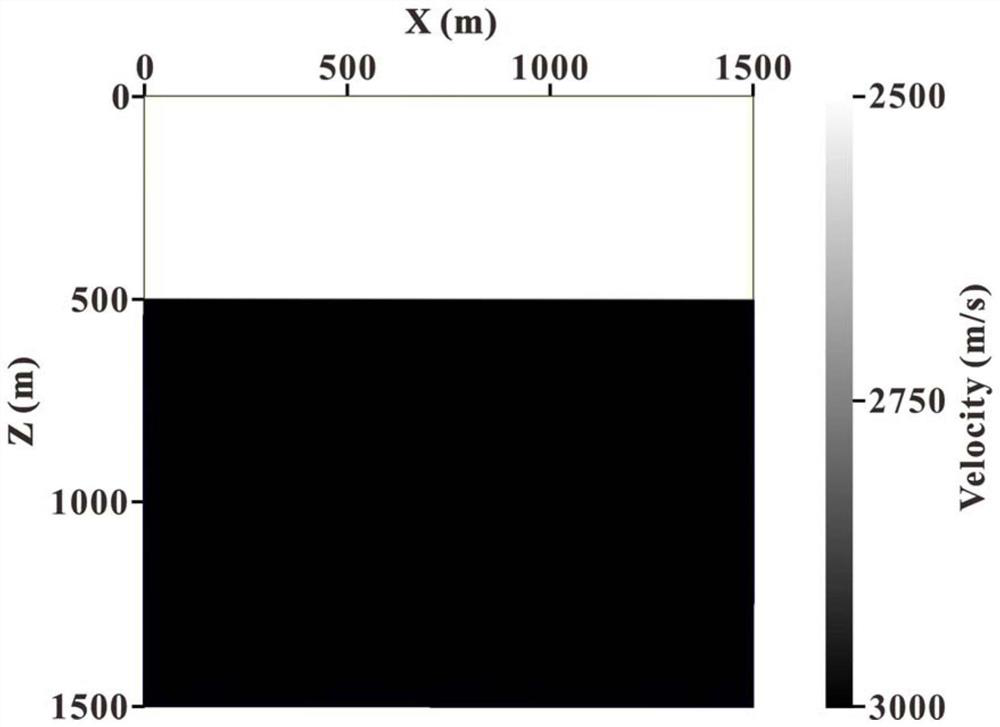
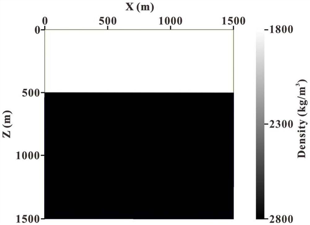
[0046] The invention proposes a correlation weighted reverse time migration imaging method based on wave field separation. The present invention uses the horizontal layered medium model to simulate the real underground medium situation in the field, and the horizontal layered medium velocity model is as follows figure 1 As shown, the velocity of the first layer is 2500m / s, the velocity of the second layer is 3000m / s, and the density model of the horizontal layered medium is as follows figure 2 As shown, the density of the first layer is 1800kg / m 3 , the density of the second layer is 2800kg / m 3 , the horizontal length of the model is 1500m, and the vertical length is 1500m.

specific Embodiment approach

[0048] (1) Based on the velocity model and density model of the above-mentioned horizontal layered medium, given the source wavelet f and the seismic record M, the shot point position is at the horizontal coordinate of 750m, a total of 301 traces are received, and the trace interval is 5m. They are all on the surface, the depth is 0m, the time sampling interval is 0.5ms, and the receiving record length is 1s. Using the first-order stress-velocity acoustic wave equation (as shown in Equation (1)) to perform finite-difference forward modeling, the source wave field S(x,z,t) at each moment can be obtained:

[0049]

[0050] In the formula, x and z are space coordinates respectively, and v x , v z They are the vibration velocity of the particle in the x and z directions, p is the stress, t is the time, ρ is the density, and v is the sound wave velocity.

[0051] (2) Taking the seismic record M as the disturbance, the finite-difference inverse time continuation is also carried...


PUM

PropertyMeasurementUnit
Densityaaaaaaaaaa
Densityaaaaaaaaaa
Horizontal lengthaaaaaaaaaa

Abstract

The invention relates to a correlation weighted reverse time migration imaging method based on wave field separation. The method belongs to the field of seismic migration imaging, and specifically comprises the following steps: in a reverse time migration imaging process, firstly realizing wave field separation of a seismic source wave field and a detection point wave field based on a Poynting vector, and obtaining upper left, lower left, upper right and right down waves of the seismic source wave field and the detection point wave field and corresponding 16 wave field separation imaging profiles; and then performing correlation processing on the 16 wave field separation imaging results and a reference profile (namely a conventional reverse time migration imaging result based on wave field separation); finally, by using the obtained correlation value as a weight to be respectively endowed with an imaging result of each wave field separation, completing the correlation weighted reverse time migration imaging based on the wave field separation. Model experiment results show that compared with a conventional reverse time migration method based on wave field separation, the method does not need to carry out manual selection and rejection on imaging results after wave field separation, and the imaging precision of reverse time migration can be remarkably improved.

Description

technical field [0001] The invention belongs to the field of seismic migration imaging, in particular to a correlation weighted reverse time migration imaging method based on wave field separation. Background technique [0002] Accurate subsurface structural migration imaging can provide a reliable guarantee for subsequent seismic data interpretation and fine description of oil and gas reservoirs, and it has always been a research hotspot in the field of seismic exploration. Reverse time migration is based on the wave equation of two-way waves, which can adapt to any complex velocity model and has no limitation on imaging angle. The migration method with the highest imaging accuracy. However, due to the need to solve the two-way wave equation, reverse time migration will produce back reflection when the seismic wave propagates to the reflecting interface, while the conventional cross-correlation imaging condition applies all wave fields to imaging without distinction, which...

Claims


Application Information

Patent Timeline
IPC IPC(8): G01V1/28G01V1/30
CPCG01V1/282G01V1/30
Inventor 解闯宋鹏王绍文毛士博姜秀萍赵波都国宁王倩倩
Owner OCEAN UNIV OF CHINA
Why Eureka
Try Eureka