Diffraction wave imaging method, device and electronic equipment

An imaging method and diffraction wave technology, applied in the field of geological exploration, can solve the problem of low accuracy of imaging results, and achieve the effect of alleviating the low accuracy

Active Publication Date: 2021-12-28
CHINA UNIV OF MINING & TECH (BEIJING)
View PDF8 Cites 0 Cited by
  • Summary
  • Abstract
  • Description
  • Claims
  • Application Information

AI Technical Summary

Problems solved by technology

[0004] The purpose of the present invention is to provide a diffraction wave imaging method, device and electronic equipment to alleviate the technical problem of low accuracy of imaging results in the diffraction wave imaging method in the prior art

Method used


Image

  • Diffraction wave imaging method, device and electronic equipment
  • Diffraction wave imaging method, device and electronic equipment
  • Diffraction wave imaging method, device and electronic equipment

Examples


Embodiment 1

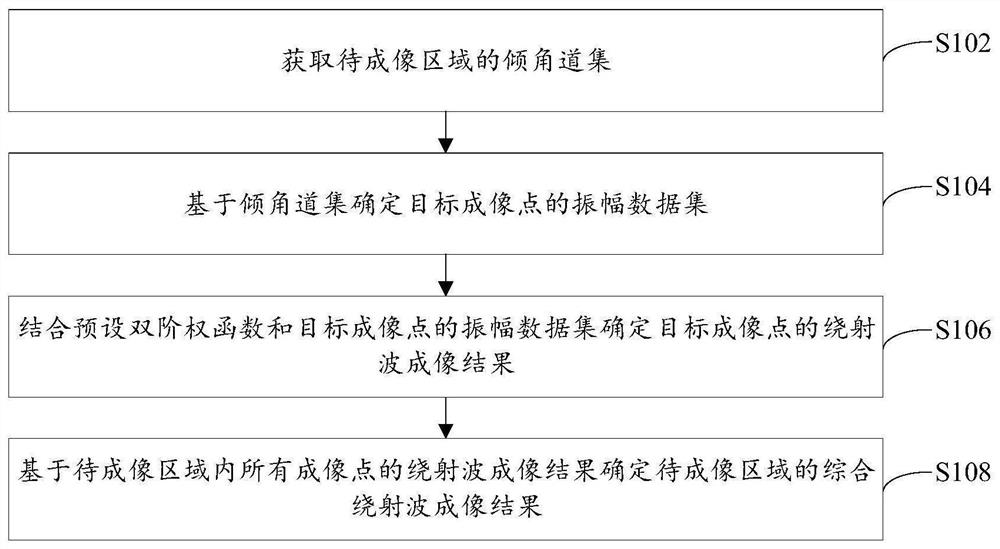
[0028] figure 1 A flowchart of a diffracted wave imaging method provided by an embodiment of the present invention, such as figure 1 As shown, the method specifically includes the following steps:

[0029] Step S102, acquiring a dip angle gather of the area to be imaged.

[0030] Specifically, to carry out diffracted wave imaging in the area to be imaged, the seismic shot data U(s, r, t) of the area must be obtained first, where s represents the shot point information, r represents the receiver point information, t represents the recording time, Then use the Kirchhoff prestack migration method to process the seismic shot data to obtain the dip angle gather S(θ, m) of the area to be imaged, where θ represents the observed dip angle, and m represents the position information of the imaging point. The dip gather is a kind of gather generated in seismic data processing. The embodiment of the present invention does not specifically limit the method of obtaining the dip gather of ...

Embodiment 2

[0063] The embodiment of the present invention also provides a diffraction wave imaging device, the diffraction wave imaging device is mainly used to implement the diffraction wave imaging method provided in the first embodiment above, the diffraction wave imaging device provided in the embodiment of the present invention is described below Make a specific introduction.

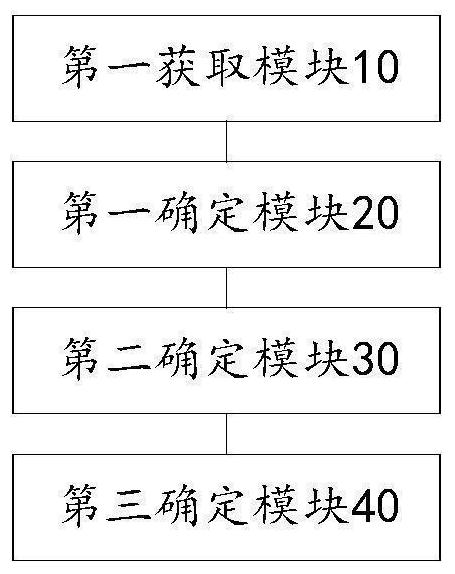
[0064] image 3 is a functional block diagram of a diffracted wave imaging device provided by an embodiment of the present invention, as shown in image 3 As shown, the device mainly includes: a first acquisition module 10, a first determination module 20, a second determination module 30, and a third determination module 40, wherein:

[0065] The first acquisition module 10 is configured to acquire a dip angle gather of the region to be imaged.

[0066] The first determining module 20 is configured to determine the amplitude data set of the target imaging point based on the dip gather; wherein, the target ...

Embodiment 3

[0080] see Figure 4 , the embodiment of the present invention provides an electronic device, the electronic device includes: a processor 60, a memory 61, a bus 62 and a communication interface 63, the processor 60, the communication interface 63 and the memory 61 are connected through the bus 62; the processor 60 is used to execute executable modules, such as computer programs, stored in memory 61 .

[0081] Wherein, the memory 61 may include a high-speed random access memory (RAM, RandomAccessMemory), and may also include a non-volatile memory (non-volatile memory), such as at least one disk memory. The communication connection between the system network element and at least one other network element is realized through at least one communication interface 63 (which may be wired or wireless), and the Internet, wide area network, local network, metropolitan area network, etc. can be used.

[0082] The bus 62 can be an ISA bus, a PCI bus or an EISA bus, etc. The bus can be d...


PUM


Abstract

The invention provides a diffracted wave imaging method, device and electronic equipment, which relate to the technical field of geological exploration, including: acquiring the dip angle gather of the area to be imaged; determining the amplitude data set of the target imaging point based on the dip angle gather; Set the double-order weight function and the amplitude data set of the target imaging point to determine the diffraction wave imaging result of the target imaging point; determine the comprehensive diffraction wave imaging result of the imaging area based on the diffraction wave imaging results of all imaging points in the imaging area. In the method of the present invention, the preset double-order weight function value corresponding to the diffracted wave amplitude is greater than the first preset threshold value, the preset double-order weight function value corresponding to the reflected wave amplitude is smaller than the second preset threshold value, and the first preset threshold value greater than the second preset threshold, so this method can effectively suppress the reflected wave energy, making the diffraction wave imaging more focused, thereby realizing high-precision imaging of the diffraction wave, and effectively alleviating the problems of the diffraction wave imaging method in the prior art. The technical problem of low accuracy of imaging results.

Description

technical field [0001] The invention relates to the technical field of geological exploration, in particular to a diffraction wave imaging method, device and electronic equipment. Background technique [0002] Discontinuous geological bodies, such as fault breakpoints, collapse columns, and formation pinch-out points, are closely related to oil and gas migration and coal mining safety. Accurate identification of these discontinuous geological bodies will help improve oil and gas extraction efficiency and reduce mining costs , to reduce the geological hazards in the process of coal mining. Geological discontinuity information is characterized by diffraction waves in the seismic wave field. Therefore, diffraction wave imaging technology can be used to obtain geological discontinuity information and improve the accuracy of seismic exploration. [0003] Traditional diffraction wave imaging methods often rely on formation angle information or need to provide filter window inform...

Claims


Application Information

Patent Timeline
Patent Type & Authority Patents(China)
IPC IPC(8): G01V1/28G01V8/10
CPCG01V1/282G01V8/10
Inventor 李闯建彭苏萍崔晓芹
Owner CHINA UNIV OF MINING & TECH (BEIJING)
Why Eureka
Try Eureka