Diffracted wave imaging method and device and electronic equipment
An imaging method and diffraction wave technology, applied in the field of geological exploration, can solve the problem of low accuracy of imaging results, and achieve the effect of alleviating the low accuracy
- Summary
- Abstract
- Description
- Claims
- Application Information
AI Technical Summary
Problems solved by technology
Method used
Image
Examples
Embodiment 1
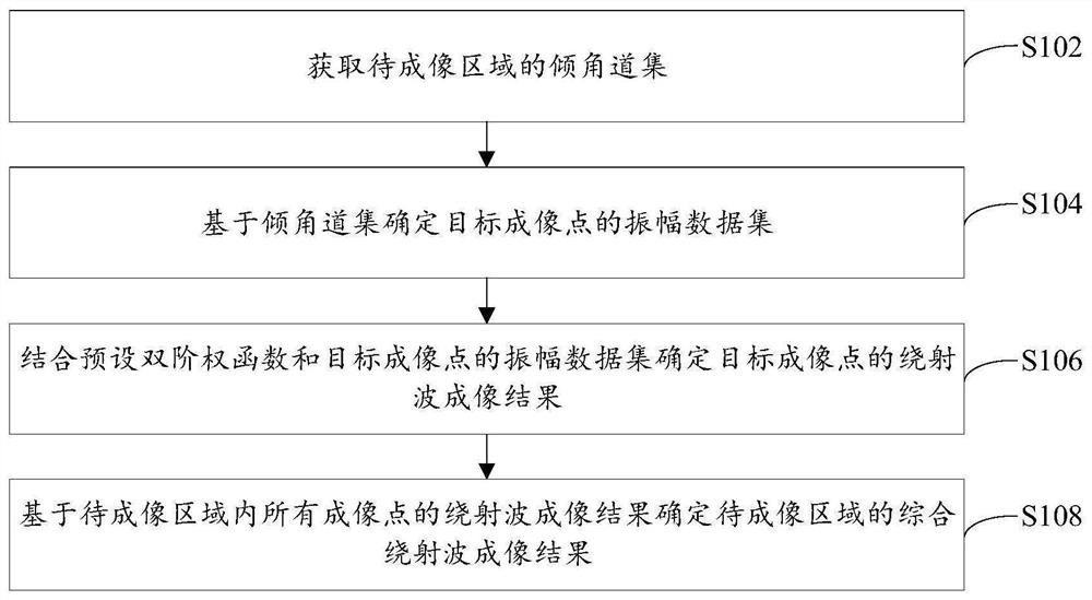
[0028] figure 1 A flowchart of a diffracted wave imaging method provided by an embodiment of the present invention, such as figure 1 As shown, the method specifically includes the following steps:
[0029] Step S102, acquiring a dip angle gather of the area to be imaged.
[0030] Specifically, to carry out diffracted wave imaging in the area to be imaged, the seismic shot data U(s, r, t) of the area must be obtained first, where s represents the shot point information, r represents the receiver point information, t represents the recording time, Then use the Kirchhoff prestack migration method to process the seismic shot data to obtain the dip angle gather S(θ, m) of the area to be imaged, where θ represents the observed dip angle, and m represents the position information of the imaging point. The dip gather is a kind of gather generated in seismic data processing. The embodiment of the present invention does not specifically limit the method of obtaining the dip gather of ...
Embodiment 2
[0063] The embodiment of the present invention also provides a diffraction wave imaging device, the diffraction wave imaging device is mainly used to implement the diffraction wave imaging method provided in the first embodiment above, the diffraction wave imaging device provided in the embodiment of the present invention is described below Make a specific introduction.
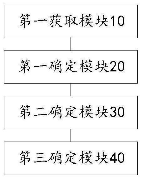
[0064] image 3 is a functional block diagram of a diffracted wave imaging device provided by an embodiment of the present invention, as shown in image 3 As shown, the device mainly includes: a first acquisition module 10, a first determination module 20, a second determination module 30, and a third determination module 40, wherein:
[0065] The first acquisition module 10 is configured to acquire a dip angle gather of the region to be imaged.
[0066] The first determining module 20 is configured to determine the amplitude data set of the target imaging point based on the dip gather; wherein, the target ...
Embodiment 3
[0080] see Figure 4 , the embodiment of the present invention provides an electronic device, the electronic device includes: a processor 60, a memory 61, a bus 62 and a communication interface 63, the processor 60, the communication interface 63 and the memory 61 are connected through the bus 62; the processor 60 is used to execute executable modules, such as computer programs, stored in memory 61 .
[0081] Wherein, the memory 61 may include a high-speed random access memory (RAM, RandomAccessMemory), and may also include a non-volatile memory (non-volatile memory), such as at least one disk memory. The communication connection between the system network element and at least one other network element is realized through at least one communication interface 63 (which may be wired or wireless), and the Internet, wide area network, local network, metropolitan area network, etc. can be used.
[0082] The bus 62 can be an ISA bus, a PCI bus or an EISA bus, etc. The bus can be d...
PUM
 Abstract
Description
Claims
Application Information
 - R&D
- Intellectual Property
- Life Sciences
- Materials
- Tech Scout
- Unparalleled Data Quality
- Higher Quality Content
- 60% Fewer Hallucinations
Browse by: Latest US Patents, China's latest patents, Technical Efficacy Thesaurus, Application Domain, Technology Topic, Popular Technical Reports.
© 2025 PatSnap. All rights reserved.Legal|Privacy policy|Modern Slavery Act Transparency Statement|Sitemap|About US| Contact US: help@patsnap.com


