Cluster system and failover method for cluster system

a cluster system and cluster system technology, applied in the field of cluster system and failover method of cluster system, can solve the problems of system halt, data may be destroyed by the plural active system, and the failure to change the failover method,

Inactive Publication Date: 2011-08-02
HITACHI LTD
View PDF12 Cites 9 Cited by
  • Summary
  • Abstract
  • Description
  • Claims
  • Application Information

AI Technical Summary

Problems solved by technology

As a result, LPARs of plural active systems may take over applications at the same time, and when such conflict of failover occurs, data may be destroyed by the plural active systems, and system halt may occur.
This is a first problem.
Therefore, for example, as described above, when applications are freely to be run in an arbitrary LPAR, since a failover method must be previously selected, the failover method cannot be changed.
Therefore, when LPAR is added or deleted, or the configuration of a physical computer that provides server virtualization environment is changed, the lack of operation performance and excessive failover performance may be provided against high availability desired by the user.
This is a second problem.
Because of this problem, when failover performance is lacking, systemdown occurs at failure (after takeover completion), while when performance is excessive, extra system resources may be consumed.
However, even when an application of a guest OS of a standby system monitors load before failover, it cannot monitor load after the failover.
Therefore, with the technology described in the U.S. Pat. No. 6,985,937, since guest OSs of standby systems are not changed, like the second problem, the lack of operation performance and excessive failover performance may be provided against high availability desired by the user.
As a result, like the second problem, failover performance may become lacking.

Method used


Image

  • Cluster system and failover method for cluster system
  • Cluster system and failover method for cluster system
  • Cluster system and failover method for cluster system

Examples


first embodiment

[0056]It should be understood that drawings and descriptions relating to the present invention are simplified to show elements suitable to clearly understand the present invention, and existing elements are omitted in such a range as not to obstruct implementation of the present. Other some conventional elements considered desirable and / or necessary to implement the present invention exist in this technology. However, these elements are known and useless to understand the present invention. Therefore, they are not described here.

[0057]In descriptions below, there are cases where each program is described using a module number in an active system (or current system), but there are cases where its description is also used as the description of a corresponding program in a standby system. Furthermore, some reference numerals in drawings that follow are the same as those in other drawings; descriptions of them are the same as those of other drawings unless otherwise noted.
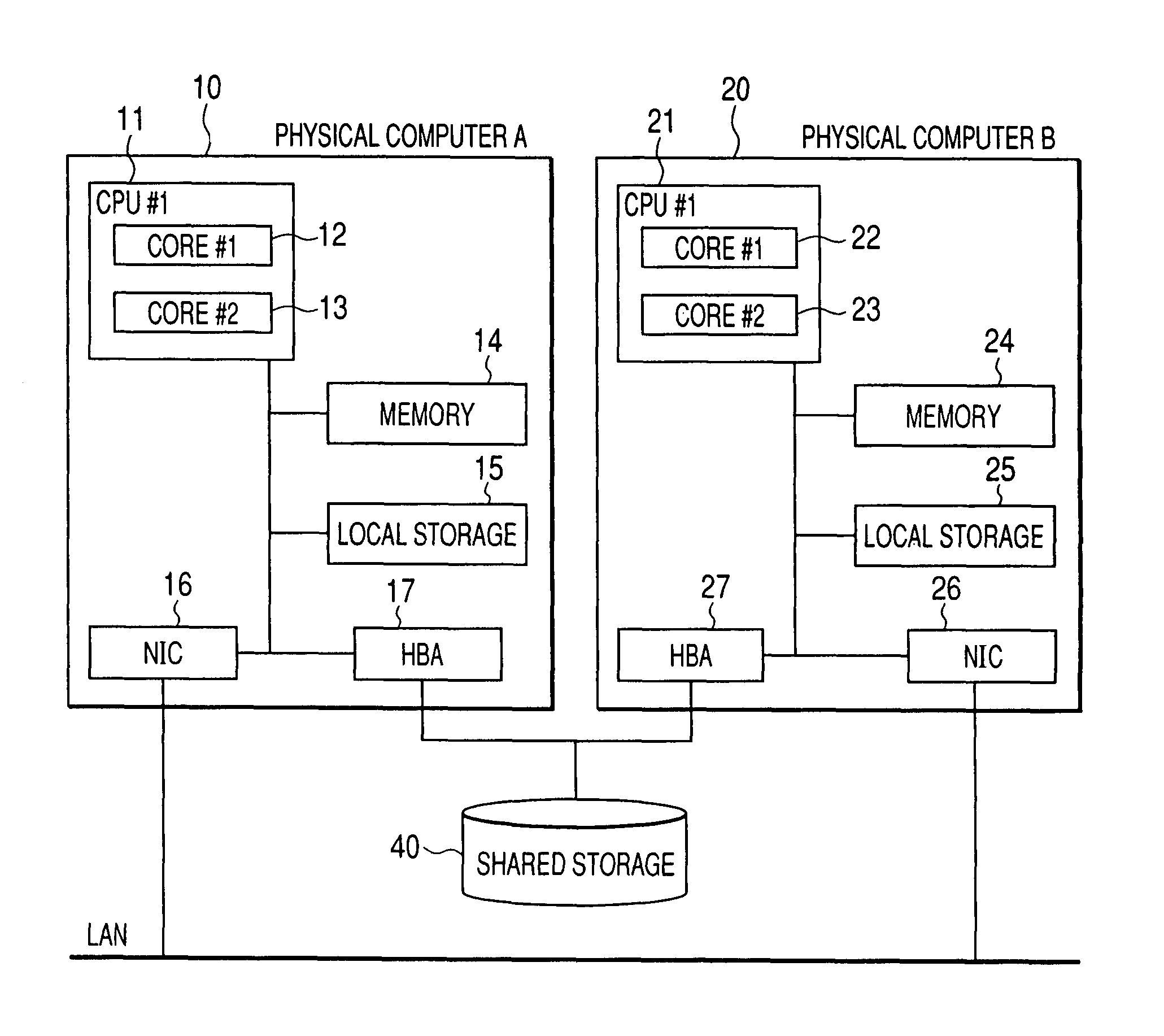
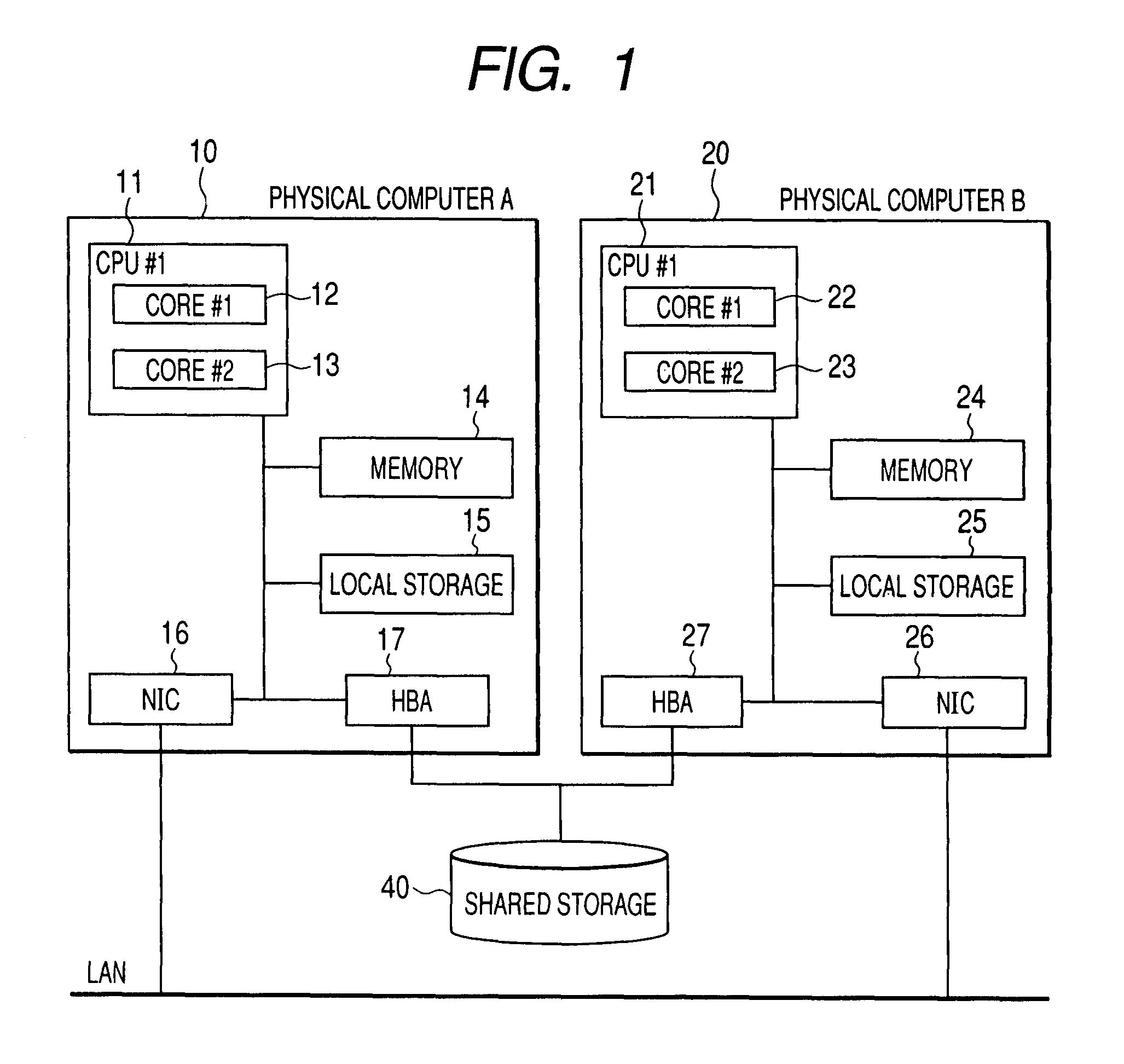
[0058]FIGS. 1 ...

second embodiment

[0123]FIGS. 14 to 18 show a second embodiment of the present invention, which is realized by partially changing the first embodiment.

[0124]FIG. 14 shows a second embodiment and is a block diagram indicating the hardware configuration of a physical computer of a server virtualization environment of the second embodiment. FIG. 14 is a partially changed version of FIG. 1 of the first embodiment. Other configurations are the same as those in the first embodiment.

[0125]In FIG. 14, a physical computer C is newly added to the configuration of the first embodiment. Individual elements of the physical computer C have the same construction as the physical computers A and B.

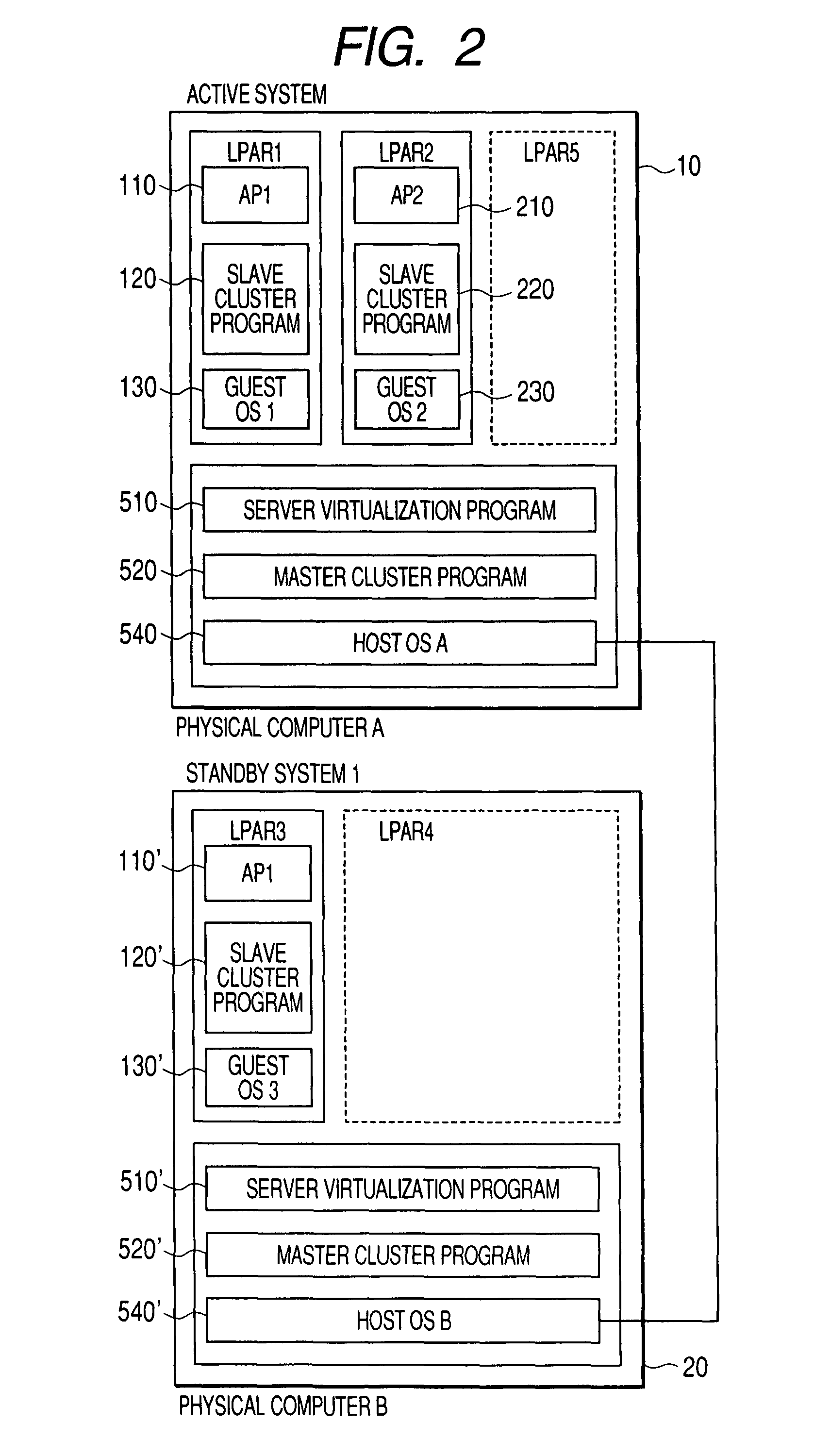
[0126]FIG. 15 is a functional block diagram centering around software of the server virtualization environment in the physical computer shown in FIG. 1. FIG. 15 is a partially changed version of FIG. 2 of the first embodiment. Other configurations are the same as those in the first embodiment.

[0127]In FIG. 15, on the physic...

third embodiment

[0134]FIGS. 19 to 23 show a third embodiment in the present invention. The third embodiment is realized by partially changing the second embodiment.

[0135]FIG. 19 is a block diagram showing a detailed configuration of software executed in the physical computer C that functions as the management server 30 of the third embodiment, and is a partially changed version of FIG. 16 of the second embodiment. Other configurations are the same as those in the second embodiment.

[0136]In FIG. 19, the system management program 610 newly includes a configuration management unit 631. The configuration management unit 631 has configuration information 632 on physical computers, host OSs, guest OSs, and applications that constitute a cluster system. The configuration information refers to information on physical or logical computer resource used in a state in which physical computers, host OSs, LPARs, guest OSs, and applications that constitute a cluster system continue to operate or remain halted. Th...


PUM


Abstract

Even when a large number of guest OSs exist, a failover method meeting high availability needed by the guest OSs is provided for the each guest OS. In the event of a physical or logical change of a system, or change of operation states, a smooth failover method can be realized by preventing the consumption of resource amounts due to excessive failover methods, and the occurrence of systemdown due to an inadequate failover method. In a server virtualization environment, in a cluster configuration having a failover method due to hot standby and cold standby, by selecting a failover method meeting high availability requirements specifying performance during failover of applications on the guest OSs, a suitable cluster configuration is realized. Failure monitoring is realized by quantitative heartbeat.

Description

CROSS REFERENCE TO RELATED APPLICATION[0001]This application is related to U.S. application Ser. No. 11 / 706876 filed on Feb. 20, 2007, the disclosure of which is hereby incorporated by reference.CLAIM OF PRIORITY[0002]The present application claims priority from Japanese application JP 2007-112056 filed on Apr. 20, 2007, the content of which is hereby incorporated by reference into this application.FIELD OF THE INVENTION[0003]The present invention relates to a computer system having high availability that takes a cluster configuration in a server virtualization environment, and more particularly to a method of performing failure monitoring and failover.BACKGROUND OF THE INVENTION[0004]The virtualization of a server computer (hereinafter referred to as server virtualization) is technology for allowing plural operating systems (hereinafter referred to as OS) to operate at the same time on a single physical computer. Logical partitioning, which is performed through a management program...

Claims


Application Information

Patent Timeline
Patent Type & Authority Patents(United States)
IPC IPC(8): G06F11/00
CPCG06F11/1484G06F11/2028G06F11/2025
Inventor BABA, TSUNEHIKOMORIKI, TOSHIOMITSUSHIMA, YUJI
Owner HITACHI LTD
Why Eureka
Try Eureka