
Ultrasonic peening treatment of assembled components

a technology of assembled components and ultrasonic peening, which is applied in the direction of vibratory devices, manufacturing tools, coatings, etc., can solve the problems of not being easily field adaptable, the residual shot in the unit is not easily retrieved from the turbine unit, and the small pieces of shot are not easily retrieved, so as to achieve the effect of without disassembly and potential

Active Publication Date: 2011-08-09
GE INFRASTRUCTURE TECH INT LLC
View PDF11 Cites 16 Cited by
  • Summary
  • Abstract
  • Description
  • Claims
  • Application Information

AI Technical Summary

Benefits of technology

Enables efficient, field-applicable ultrasonic peening of assembled turbine rotor components, preventing shot media contamination and ensuring complete media removal, thereby enhancing fatigue life and preventing premature failure.

Problems solved by technology

In a field application, however, a conventional shot peen process scatters shot widely about the work area, and the small pieces of shot are not easily retrieved from the turbine unit.
Residual shot in the unit poses a threat to the operation of the turbine.
Forms of peening other than conventional exist, such as laser shock, water cavitation shock, and the like; however, these forms are either very expensive or not readily field adaptable.
As a consequence, the existing applications are not suitable for use in situ.
Additionally, the existing applications lack equipment mobility and are typically unable to operate on a vertically rotating component.
With most processes, a line-of-sight is not available while the rotor is still in the casing and / or the rotor assembly is still intact.
An additional concern with conventional shot peening is that some of the shot would remain in the assembled rotor or casing, causing subsequent premature failure of other parts, such as buckets, nozzles or bearings, upon return to service.

Method used


Image

  • Ultrasonic peening treatment of assembled components
  • Ultrasonic peening treatment of assembled components
  • Ultrasonic peening treatment of assembled components

Examples


Embodiment Construction

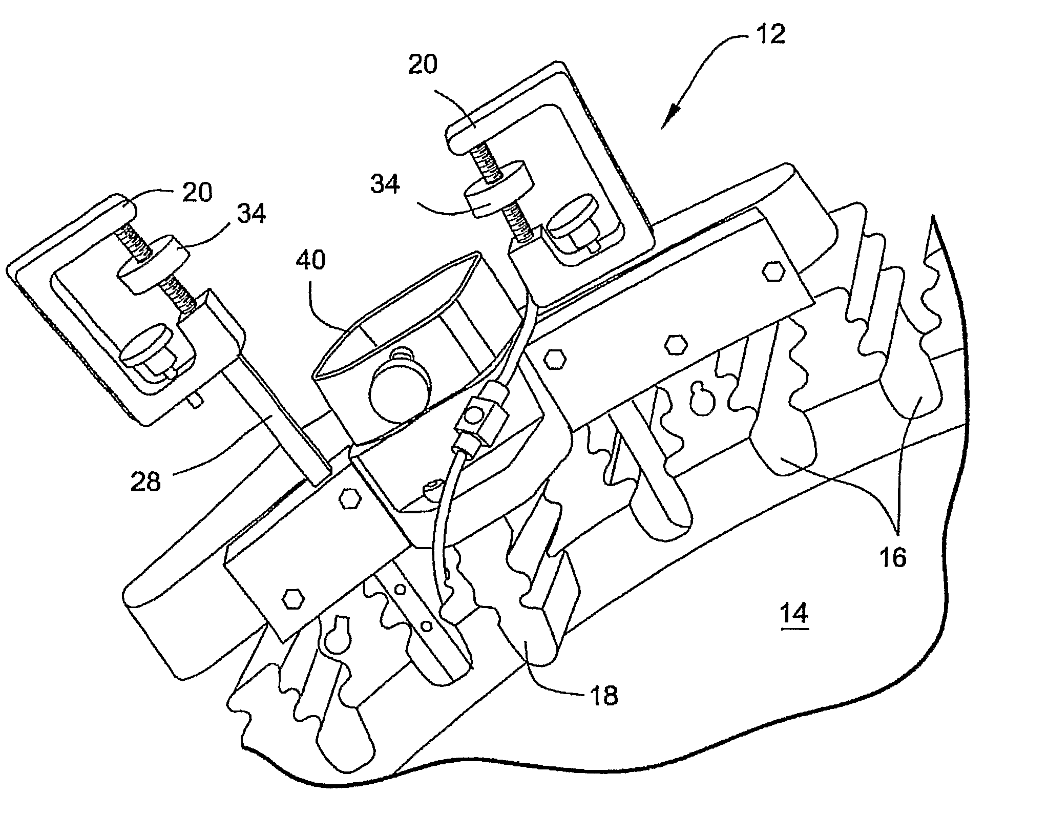
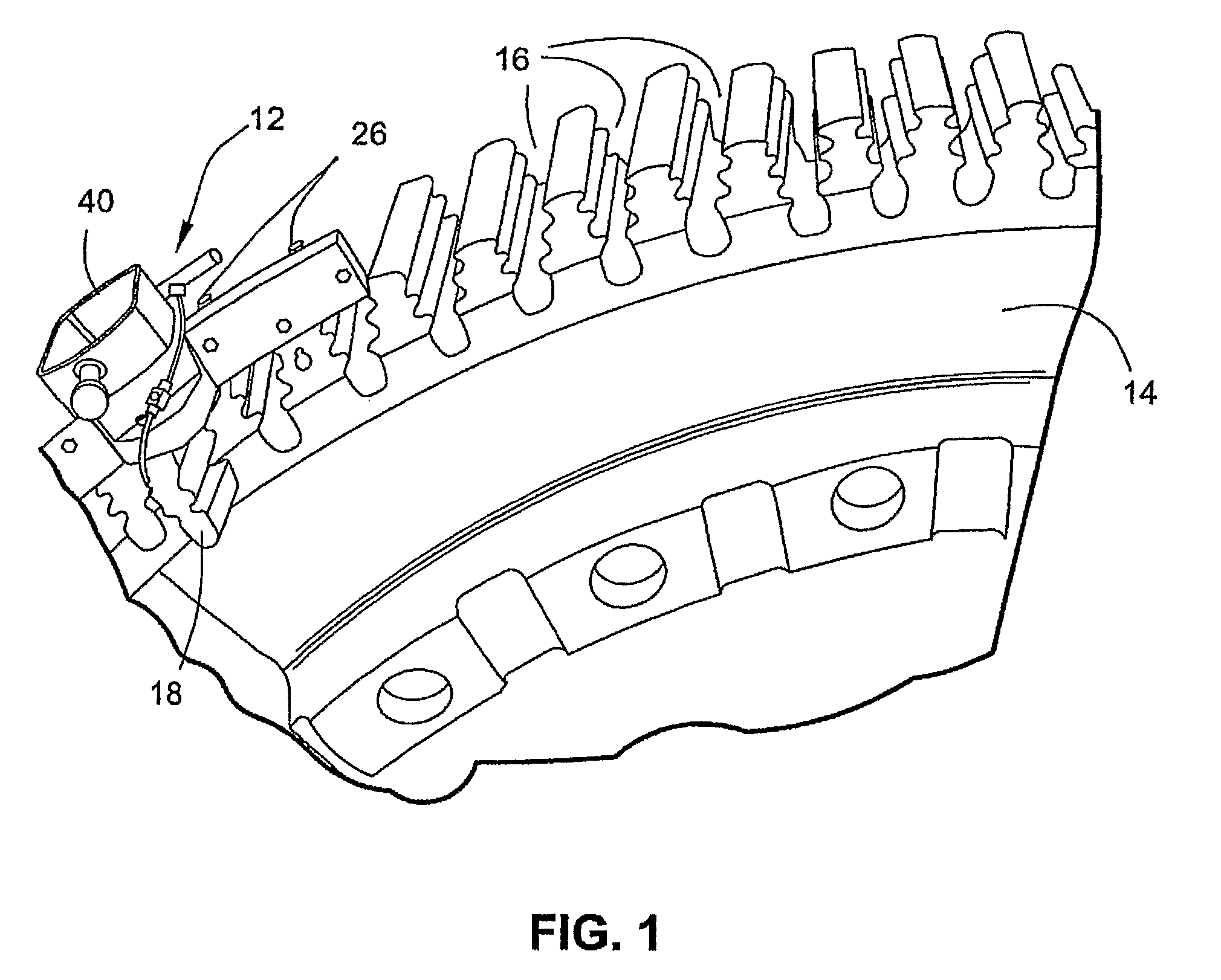
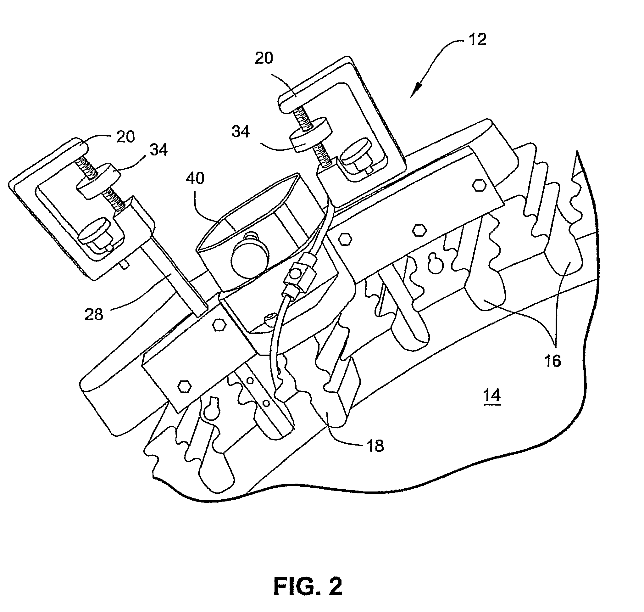
[0019]With reference to FIGS. 1 and 2, a system for ultrasonic peening treatment of assembled turbine rotor components includes a frame 12 attachable to an assembled turbine rotor component. The rotor component shown in FIGS. 1 and 2 is a section of a turbine wheel 14. A typical turbine wheel 14 includes a plurality of dovetail slots 16 that receive correspondingly-shaped dovetails of turbine blades (not shown). The frame 12 includes a dovetail-shaped attachment 18 that slides axially into a dovetail slot 16 on the rotor wheel 14. Screws or other suitable securing structure fix the frame 12 in the slot 16.

[0020]As shown in FIG. 2, at least one insert member 20, possibly two or three, is selectively engageable with the frame 12 and the rotor wheel 14. More particularly, as shown in FIG. 3, the rotor wheel 14 includes a cooling passage defined by a cooling groove 22 extending circumferentially around the rotor wheel 14 and by an aperture 24 in each of the dovetail slots 16 opening to ...


PUM

PropertyMeasurementUnit
residual compressive stressaaaaaaaaaa
compressive stressaaaaaaaaaa
shapeaaaaaaaaaa

Abstract

Ultrasonic peening treatment is desirable where an application of a compressive stress is helpful to reduce the incidence of crack formation on highly stressed parts. Ultrasonic peening treatment can be performed in field applications without requiring a rotor to be removed from the machine. The system includes an acoustic element that excites peening media within a peen chamber. A frame is attachable to an assembled turbine rotor component and includes support structure engageable with the acoustic element. The frame is cooperable with a chamber tooling that defines and encloses the peen chamber together with the turbine rotor component.

Description

CROSS-REFERENCES TO RELATED APPLICATIONS[0001]This application is the U.S. national phase of International Application No. PCT / US2006 / 018469 filed 12 May 2006 which designated the U.S. and claims priority to U.S. Provisional Patent Application Ser. No. 60 / 680,039 filed 12 May 2005, the entire contents of each of which are hereby incorporated by reference.BACKGROUND OF THE INVENTION[0002]The present invention relates to peening of assembled rotor parts while still in the casing or unit rotor and, more particularly, to ultrasonic peening treatment of rotor components for gas turbines, steam turbines or hydro machines wherever shot peening is deemed necessary or desirable.[0003]It is generally recognized that fatigue life for certain materials is enhanced when parts are shot peened. Peening induces a residual compressive stress that retards crack initiation. The most widely used peening technology involves a large quantity (many pounds) of small sized metallic or ceramic ‘shot,’ which ...

Claims


Application Information

Patent Timeline
Patent Type & Authority Patents(United States)
IPC IPC(8): B24C1/00B05D3/12C21D7/00
CPCB24C1/10B24C5/005Y10T29/479C21D7/00B05D3/12B24C1/00C21D7/06
Inventor STONITSCH, RAYMOND JOSEPHBEAGLE, DIANE MARIEDUCHAZEAUBENEIX, JEAN-MICHELCHEPPE, PATRICKJACOB, PHILIPPEDESFONTAINE, VINCENT
Owner GE INFRASTRUCTURE TECH INT LLC
Learn More