Structure and method for forming power devices with carbon-containing region

a technology of carbon-containing region and structure, applied in the field of simiconductor technology, can solve the problems of obtaining a higher breakdown voltage at the expense of higher on-resistance (rdson)

Active Publication Date: 2011-08-09
SEMICON COMPONENTS IND LLC
View PDF31 Cites 100 Cited by
  • Summary
  • Abstract
  • Description
  • Claims
  • Application Information

AI Technical Summary

Problems solved by technology

In such conventional power devices, obtaining a higher breakdown voltage often comes at the expense of higher on-resistance (Rdson).

Method used


Image

  • Structure and method for forming power devices with carbon-containing region
  • Structure and method for forming power devices with carbon-containing region
  • Structure and method for forming power devices with carbon-containing region

Examples


Embodiment Construction

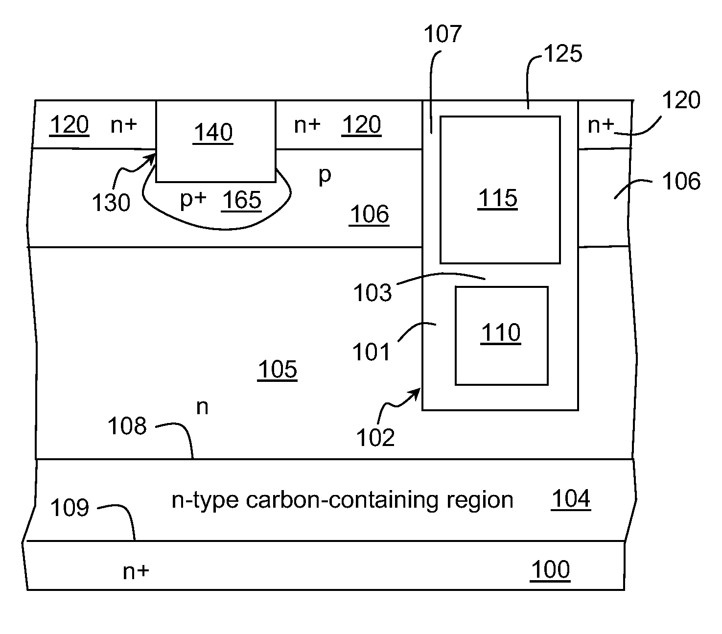
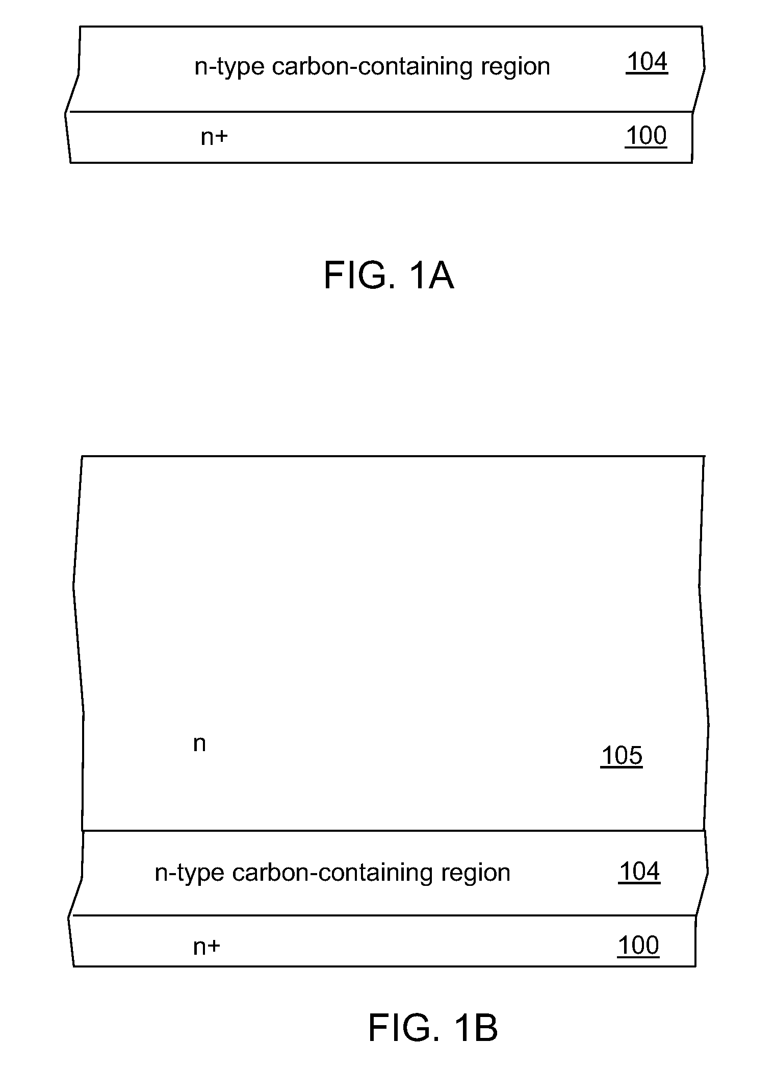
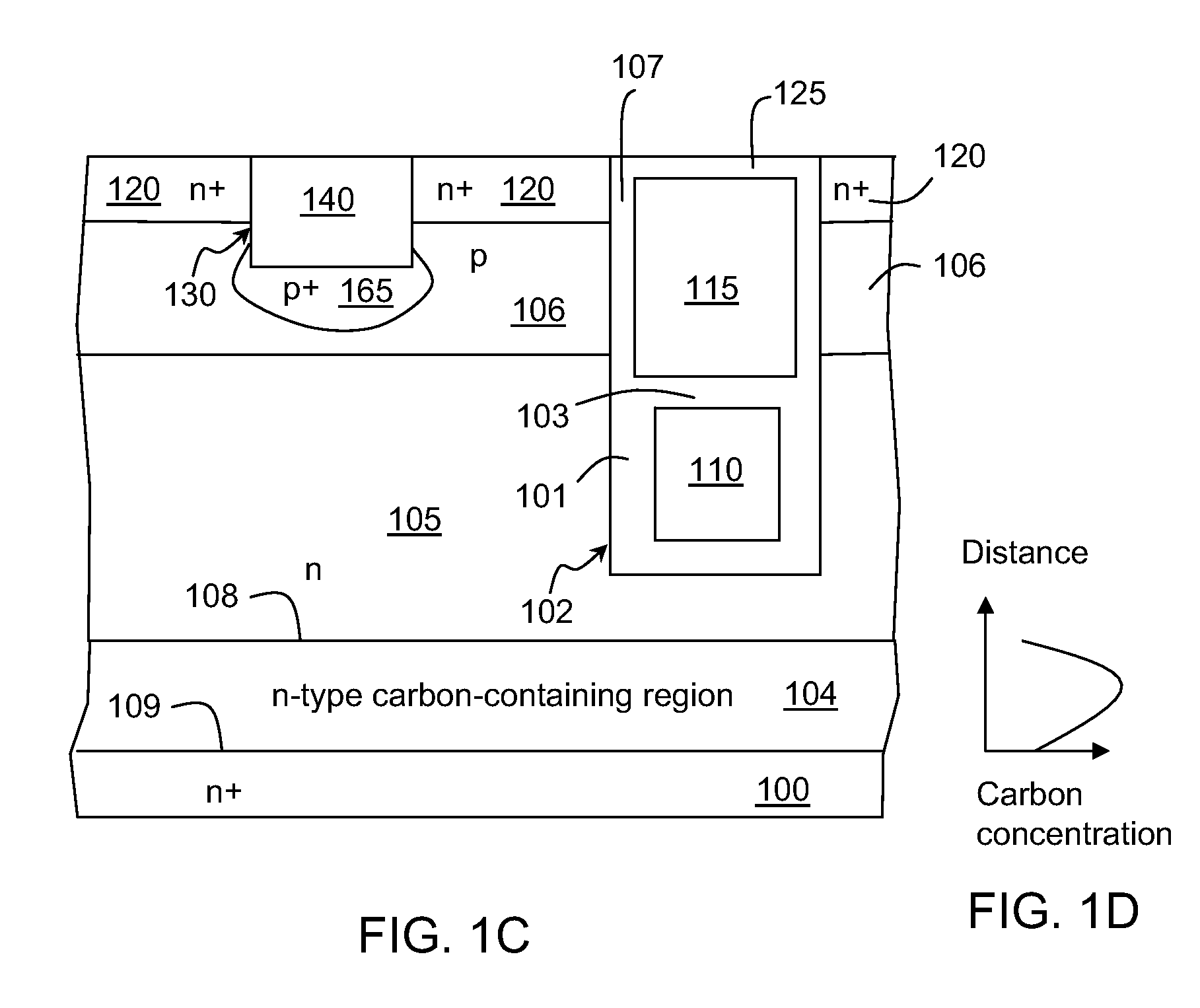
[0028]According to the embodiments of the present invention, techniques directed to integrated circuits and their processing are disclosed. More particularly, the invention provides methods and devices for power field effect transistors (FETs) which include a carbon-containing layer. The carbon-containing layer is configured to provide a higher breakdown voltage and other advantageous features described more fully below. Merely by way of example, the invention has been described in the context of trench power MOSFETs, but it would be recognized that the invention has a much broader range of applicability. For example, the invention can be applied to planar power MOSFETs as well as to trench gate and planar gate IGBTs.

[0029]Depending on the embodiments, the carbon-containing layer may be formed in the drift region a trench gate FET. Alternatively, the carbon containing layer may abut sidewalls of trenches extending into the drift region. In some embodiments, the carbon-containing lay...


PUM


Abstract

A field effect transistor (FET) includes body regions of a first conductivity type over a semiconductor region of a second conductivity type. The body regions form p-n junctions with the semiconductor region. Source regions of the second conductivity type extend over the body regions. The source regions form p-n junctions with the body regions. Gate electrodes extend adjacent to but are insulated from the body regions by a gate dielectric. A carbon-containing region extends in the semiconductor region below the body regions.

Description

CROSS-REFERENCES TO RELATED APPLICATIONS[0001]This application claims the benefit of U.S. Provisional Application No. 61 / 013,953, filed Dec. 14, 2007, which is incorporated herein by reference in its entirety for all purposes.BACKGROUND OF THE INVENTION[0002]The present invention relates in general to semiconductor technology and more particularly to semiconductor power devices with carbon-doped region and method of forming the same.[0003]Generally, an n-channel trench-gate power MOSFET includes an n-type substrate on which an n-type epitaxial layer is formed. The substrate embodies the drain of the MOSFET. A p-type body region extends into the epitaxial layer. Trenches extend through the body region and into the portion of the epitaxial layer bounded by the body region and the substrate (commonly referred to as the drift region). A gate dielectric layer is formed on the sidewalls and bottom of each trench. Source regions flank the trenches. Heavy body regions are formed within the ...

Claims


Application Information

Patent Timeline
Patent Type & Authority Patents(United States)
IPC IPC(8): H01L29/66
CPCH01L21/046H01L29/161H01L29/165H01L29/66712H01L29/66734H01L29/7802H01L29/7813H01L29/407H01L29/41766H01L29/42368H01L2924/0002H01L2924/00
Inventor PAN, JAMES
Owner SEMICON COMPONENTS IND LLC
Why Eureka
Try Eureka