Shock-absorbing structure for storage apparatus

a technology of shock-absorbing structure and storage apparatus, which is applied in the direction of electrical apparatus casings/cabinets/drawers, furniture parts, instruments, etc., can solve the problems of limited shock-absorbing effect, inability to absorb vertical but not horizontal impact energy, and the disk will surely touch the disk directly, etc., to achieve the effect of strengthening the strength of the penetration trough, and increasing the life of the present invention

Active Publication Date: 2011-08-09
ACER INC
View PDF23 Cites 21 Cited by
  • Summary
  • Abstract
  • Description
  • Claims
  • Application Information

AI Technical Summary

Benefits of technology

[0006]An objective of the present invention is to provide a shock-absorbing structure for a storage apparatus, which can absorb vibration energy imposed on the storage apparatus by adapting a plurality of penetrating troughs on a first arm and a second arm used for securing the storage apparatus with buffer members therein. Thereby, the vibration energy received by the storage apparatus can be absorbed, and the lifetime thereof can be increased.
[0007]Another objective of the present invention is to provide a shock-absorbing structure for a storage apparatus. By using reinforcement parts adapted in the penetrating troughs of the arms, which are used for securing the storage apparatus, the strength of the penetrating troughs can be reinforced, and the lifetime of the present invention can be increased.
[0008]A further objective of the present invention is to provide a shock-absorbing structure for a storage apparatus. By adapting pillars inside of the arms, which are used for securing the storage apparatus, and by inserting said pillars into the securing holes outside of the storage apparatus, the storage apparatus can be secured.
[0009]Still another objective of the present invention is to provide a shock-absorbing structure for a storage apparatus. By adapting a plurality of salient parts on the upper and lower edges as well as on the outer side of the arms, which are used for securing the storage apparatus, the friction produced when the storage apparatus is installed in a holding space will be reduced owing to the salient parts. Thereby, the smoothness when installing the storage apparatus is enhanced. Besides, the salient parts can produce a gap between the storage apparatus and the holding space. Hence, the heat-dissipating efficiency of the storage apparatus can be increased, and the lifetime of the storage apparatus can be increased as well.
[0010]The shock-absorbing structure for a storage apparatus according to the present invention includes a first arm and a second arm positioned on both sides of the storage apparatus for securing the storage apparatus. The first and the second arms have one or more first penetrating troughs and one or more penetrating troughs, respectively, and a plurality of first buffer members adapted in the first and the second penetrating troughs, respectively. By coordination of the penetrating troughs and the buffer members, shock energy imposed on the storage apparatus can be absorbed. Thereby, the lifetime of the storage apparatus can be increased.
[0011]Besides, according to the present invention, reinforcement parts are adapted on the sidewalls of the penetrating troughs. Thereby, the strength of the penetrating troughs can be reinforced, and the lifetime of the present invention can be increased. Moreover, a plurality of salient parts is adapted on the upper and lower edges as well as on the outer side of the first and the second arms. By using said salient parts, the contact areas for installation can be reduced. Thereby, the friction is reduced and hence the smoothness when installing the storage apparatus is enhanced. Besides, the salient parts can produce a gap between the storage apparatus and the holding space. Thus, the heat-dissipating efficiency of the storage apparatus can be increased, and the lifetime of the storage apparatus can be increased as well.

Problems solved by technology

If the storage apparatus is vibrated by external forces, the read / write head will surely touch the disk directly and bring damages to the disk or to the read / write head.
However, because the buffer member is installed at the bottom of the storage apparatus, only vertical but not horizontal impact energy can be absorbed.
Hence, the shock-absorbing effect is limited.
When the storage apparatus is impacted by external forces, the storage apparatus will move arbitrarily in the holding space, resulting in secondary impact on the storage apparatus and increasing possibility of damage on the storage apparatus.
Besides, because the buffer member is installed at the bottom of the storage apparatus, the storage apparatus cannot dissipate heat effectively.
Hence, the lifetime of the storage apparatus will be affected.
Thereby, the techniques according to the prior art can neither protect the storage apparatus effectively nor lengthen the lifetime thereof.
Besides, the salient parts can produce a gap between the storage apparatus and the holding space.

Method used


Image

  • Shock-absorbing structure for storage apparatus
  • Shock-absorbing structure for storage apparatus
  • Shock-absorbing structure for storage apparatus

Examples


Embodiment Construction

[0019]In order to make the structure and characteristics as well as the effectiveness of the present invention to be further understood and recognized, the detailed description of the present invention is provided as follows along with preferred embodiments and accompanying figures.

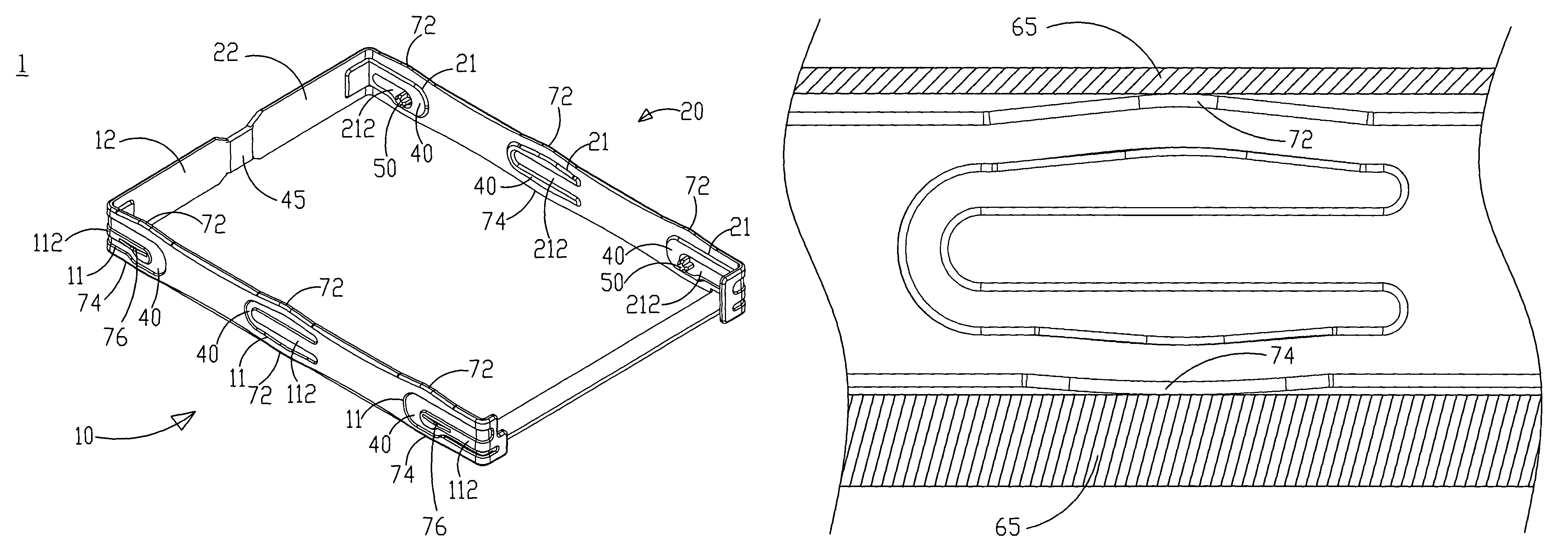
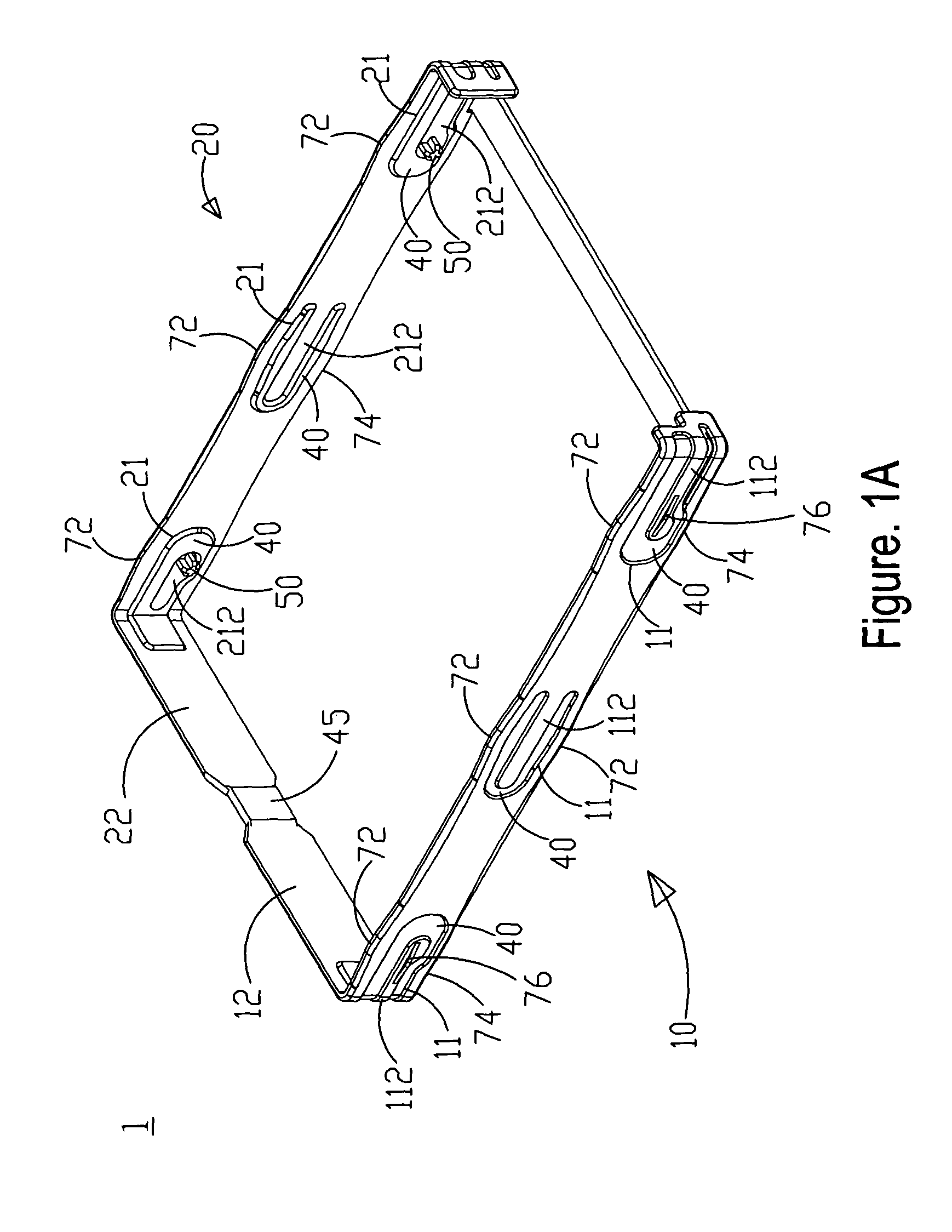
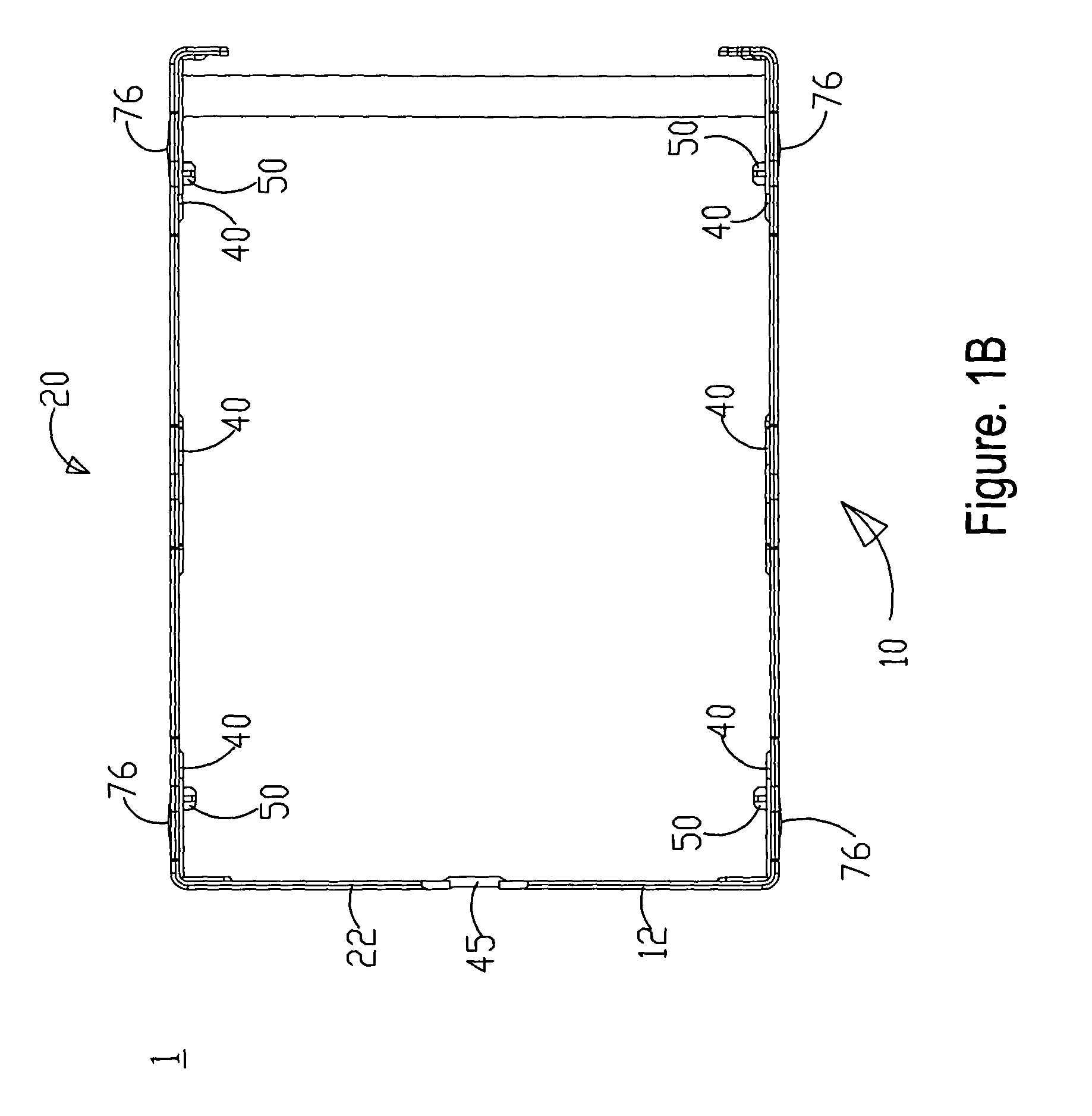
[0020]FIGS. 1A, 1B, and 2 show a three-dimensional view and a top view of a shock-absorbing structure, and a three-dimensional view of a storage apparatus according to a preferred embodiment of the present invention. As shown in the figures, the shock-absorbing structure for a storage apparatus according to the present invention includes a frame 1 used for securing a storage apparatus 30. The frame 1 includes a first arm 10 and a second arm 20, which are located on both sides of the storage apparatus 30, and are used for securing a storage apparatus 30. The first and the second arms 10, 20 have one or more first penetrating troughs 11 and one or more second penetrating troughs 21, respectively. A first tr...


PUM


Abstract

The present invention relates to a shock-absorbing structure for a storage apparatus, which includes a first arm and a second arm. The first and the second arms are secured on both sides of a storage apparatus. One or more first penetrating troughs and one or more second penetrating troughs are adapted on the first and the second arms, respectively. A plurality of first buffer members is adapted on the first and the second penetrating troughs. By securing the storage apparatus using the present invention, shocks imposed on the storage apparatus can be eased, and thereby the lifetime can be increased.

Description

FIELD OF THE INVENTION[0001]The present invention relates to a shock-absorbing structure, and particularly to a shock-absorbing structure for a storage apparatus.BACKGROUND OF THE INVENTION[0002]With the trend of the era, the design of technological products changes accordingly. For example, for better portability, modern electronic products are designed small. Owing to this trend, desktop computers have evolved into modern notebook computers, which provide a best evidence for the shrinkage trend in electronic products for better portability.[0003]Take notebook computer for example. Modern notebook computers have a storage apparatus such as a hard disk. However, a hard disk comprises a read / write head and reads or writes data by closing to a disk by a small distance. If the storage apparatus is vibrated by external forces, the read / write head will surely touch the disk directly and bring damages to the disk or to the read / write head. Shock-absorbing protection is provided to current...

Claims


Application Information

Patent Timeline
Patent Type & Authority Patents(United States)
IPC IPC(8): G06F1/16
CPCG11B33/08
Inventor KUO, YAN-LIN
Owner ACER INC
Why Eureka
Try Eureka