Multiple ion isolation in multi-reflection systems

a multi-reflection system and ion isolation technology, applied in the field of charged particle traps, can solve the problems of limiting the useful time period, unable to select ions with high mass resolution, and further to be gained, so as to reduce the required separation in time

Active Publication Date: 2011-08-16
THERMO FISHER SCI BREMEN
View PDF24 Cites 34 Cited by
  • Summary
  • Abstract
  • Description
  • Claims
  • Application Information

AI Technical Summary

Benefits of technology

[0023]Interference-free fragmentation of multiple ion species of interest could be implemented by ejecting each of them sequentially into the fragmentation cell with a separation in time that is greater than the width of distributions of residence times of these species and their fragments in the fragmentation cell. Multiple ion species of interest may be ejected into the fragmentation cell together for fragmenting as a single batch. Alternatively, each of the species of interest could be diverted into its own dedicated cell for fragmentation and / or trapping which would allow a reduction in the required separation in time, and also allow parallel processing of all these species.

Problems solved by technology

Because of this, application of a single frequency sinusoidal excitation field to the trap will excite ions with a range of mass to charge ratios and cannot be used to select ions with high mass resolution.
Both of these requirements are usually limited by ion optical imperfections of the trap, which set a limit on the useful time period—there is nothing further to be gained in continuing to oscillate the ions once the resolution limit of the trap has been reached.
Prior art methods of ion ejection suffer from a serious disadvantage, in that ions of only one mass to charge ratio (at high resolution), or ions of a continuous range of adjacent mass to charge ratios (at low resolution) are selected at a time.
However, to acquire an extended mass spectrum at high resolution or multiple MS / MS experiments would require a great many trap fills, and a long elapsed time.
If the sample material to be analysed is limited, it might be that only a small mass range could be analysed using this method.
In the case of low resolution mass detection of a range of adjacent mass to charge ratios, there is an additional problem.
This is several orders of magnitude shorter than the response time of typical detectors and thus limits resolution of ions of adjacent mass to charge ratios of significantly differing abundances.

Method used


Image

  • Multiple ion isolation in multi-reflection systems
  • Multiple ion isolation in multi-reflection systems
  • Multiple ion isolation in multi-reflection systems

Examples


Embodiment Construction

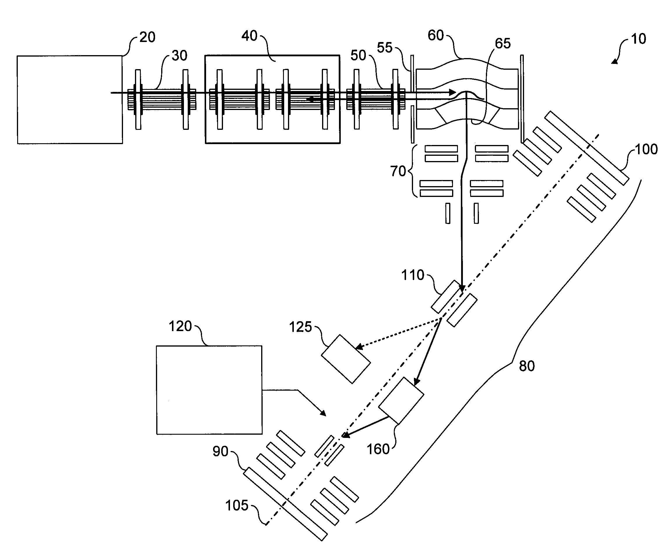
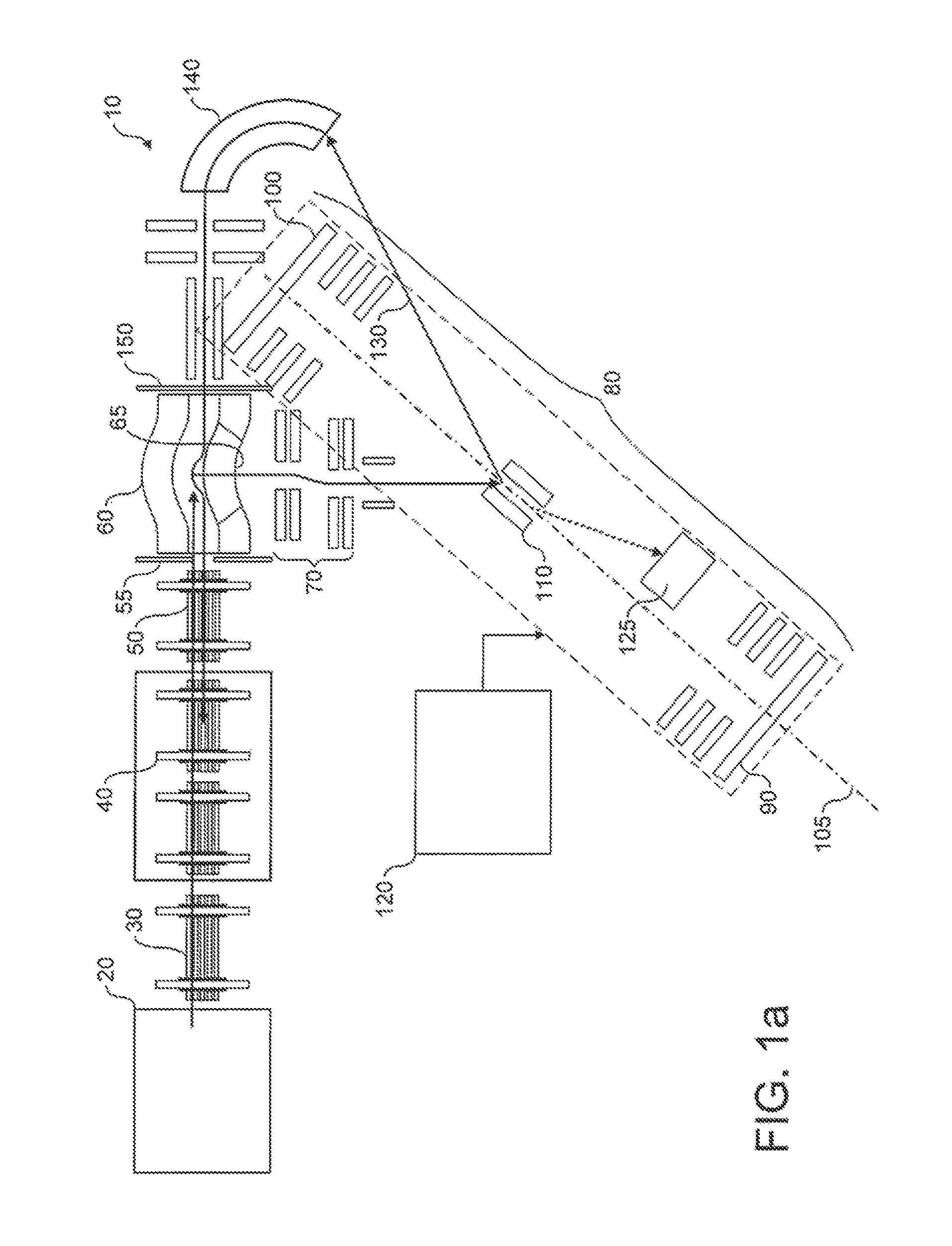
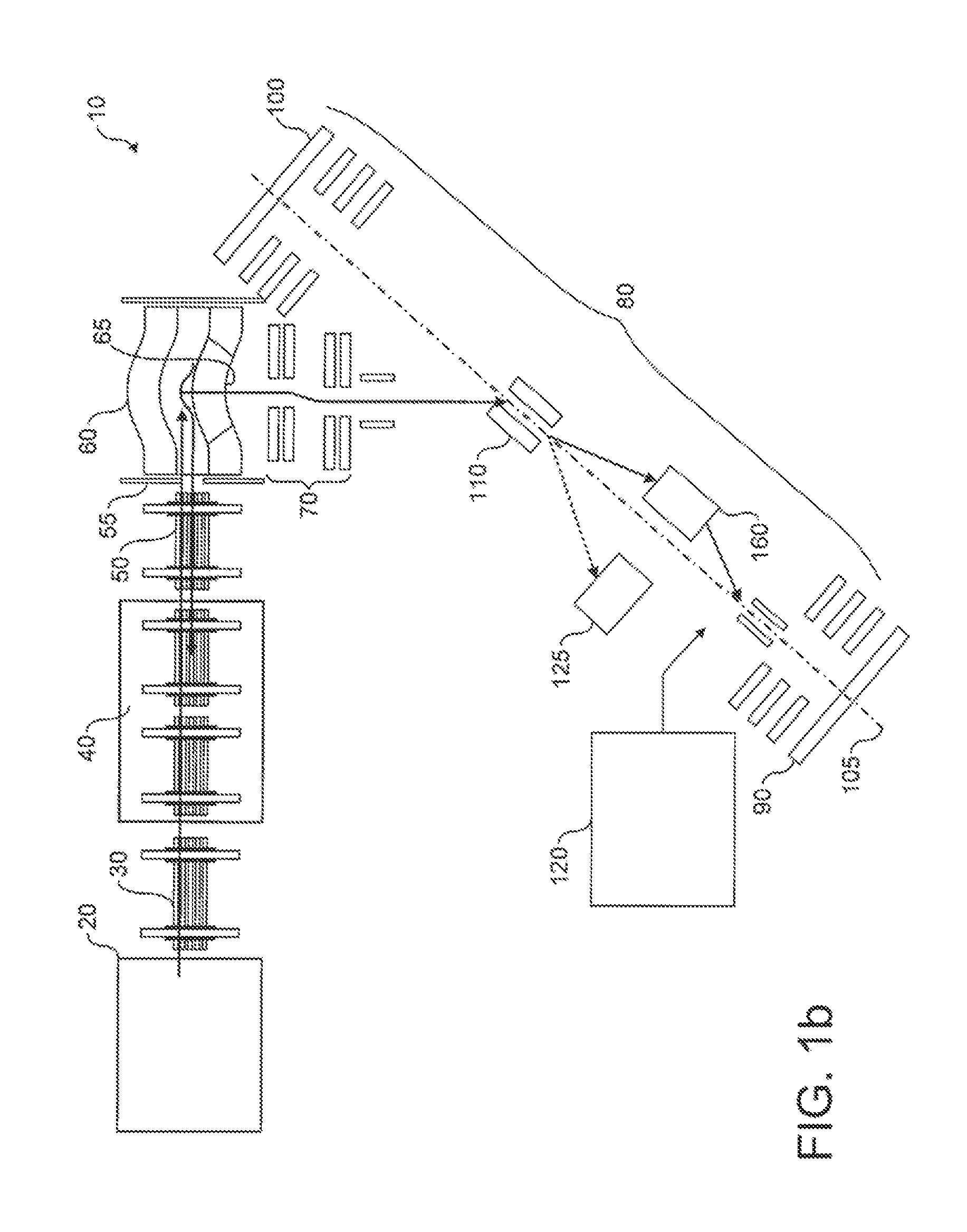
[0031]FIG. 1a shows an embodiment of a mass spectrometer 10 in accordance with the present invention. The mass spectrometer comprises an external ionisation source 20, such as an electrospray ion source or a MALDI ion source, which generates a continuous or pulsed stream of charged particles to be analysed. The charged particles pass through first ion optics 30 and into a pre-trap 40. The ions are confined in the pre-trap 40 to permit accumulation of ions from the ion source 20, after which they are injected into an rf-only injection trap 60, via second ion optics 50. The injection trap 60 may be a linear quadrupole trap, a linear octapole trap, and so forth. In the preferred embodiment, however, a curved linear trap, preferably with rf switching, is employed. This trap receives ions from the pre-trap 40 through a first entrance aperture 55, stores them in the curved linear trap, and then ejects them orthogonally through an ion exit aperture 65. Ions leaving the ion exit aperture 65...


PUM


Abstract

This invention relates to a method of operating a charged particle trap in which ions undergo multiple reflections back and forth and / or follow a closed orbit around, usually, a set of electrodes. The invention allows high-performance isolation of multiple ion species for subsequent detection or fragmentation by deflecting ions out of the ion trap according to a timing scheme calculated with reference to the ions' periods of oscillation within the ion trap.

Description

FIELD OF THE INVENTION[0001]This invention relates to a charged particle trap in which ions undergo multiple reflections back and forth and / or follow a closed orbit under the influence of a set of electrodes. The invention also relates in particular to a method of operating such a trap and allows high-performance isolation of multiple ion species for subsequent detection or fragmentation.BACKGROUND OF THE INVENTION[0002]There are currently many known arrangements and techniques for trapping or storing charged particles for the purposes of mass spectrometry. In some such arrangements, for example 3-D RF traps, linear multipole RF traps, and the more recently developed “Orbitrap”, ions injected into or formed within the trap oscillate within the trap with simple harmonic motion. In that case, ions may be selected for onward transmission to other traps, for mass analysis / detection, and so forth, by applying oscillating fields to the trap. This is because all of the ions of a given mass...

Claims


Application Information

Patent Timeline
Patent Type & Authority Patents(United States)
IPC IPC(8): H01J49/06H01J49/26H01J49/40
CPCH01J49/0031H01J49/0081H01J49/422H01J49/4245H01J49/427
Inventor MAKAROV, ALEXANDER ALEKSEEVICHGIANNAKOPULOS, ANASTASSIOS
Owner THERMO FISHER SCI BREMEN
Why Eureka
Try Eureka