Magnetic resonance apparatus with table movement controlled dependent on magnetic field distribution

a magnetic field and table movement technology, applied in the field of magnetic field devices, can solve problems such as uncomfortable feelings in patients, and achieve the effect of minimizing the side effects of entering or exiting the patient bed into or from the patient chamber

Active Publication Date: 2011-08-16
SIEMENS HEALTHCARE GMBH
View PDF4 Cites 1 Cited by
  • Summary
  • Abstract
  • Description
  • Claims
  • Application Information

AI Technical Summary

Benefits of technology

[0006]An object of the present invention is therefore to provide a magnetic resonance device in which side-effects occurring on entry or exit of the patient bed into or from the patient chamber are minimized.

Problems solved by technology

Since human beings are by and large diamagnetic, a location-dependent diamagnetic force is generated on the human body by this field distribution, which triggers the uncomfortable feelings in the patient.

Method used


Image

  • Magnetic resonance apparatus with table movement controlled dependent on magnetic field distribution
  • Magnetic resonance apparatus with table movement controlled dependent on magnetic field distribution
  • Magnetic resonance apparatus with table movement controlled dependent on magnetic field distribution

Examples


Embodiment Construction

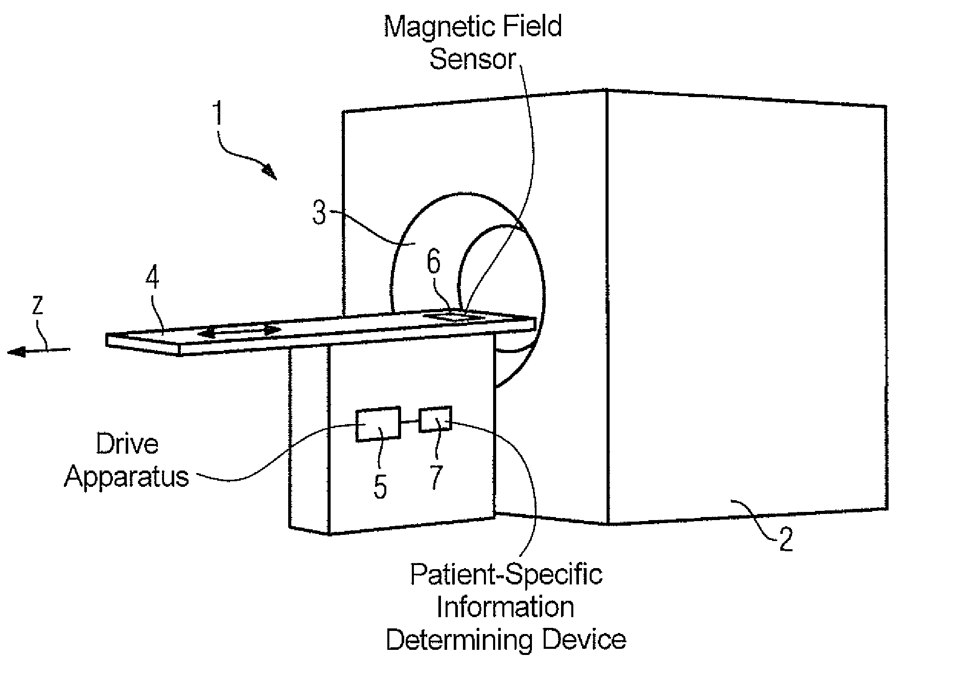
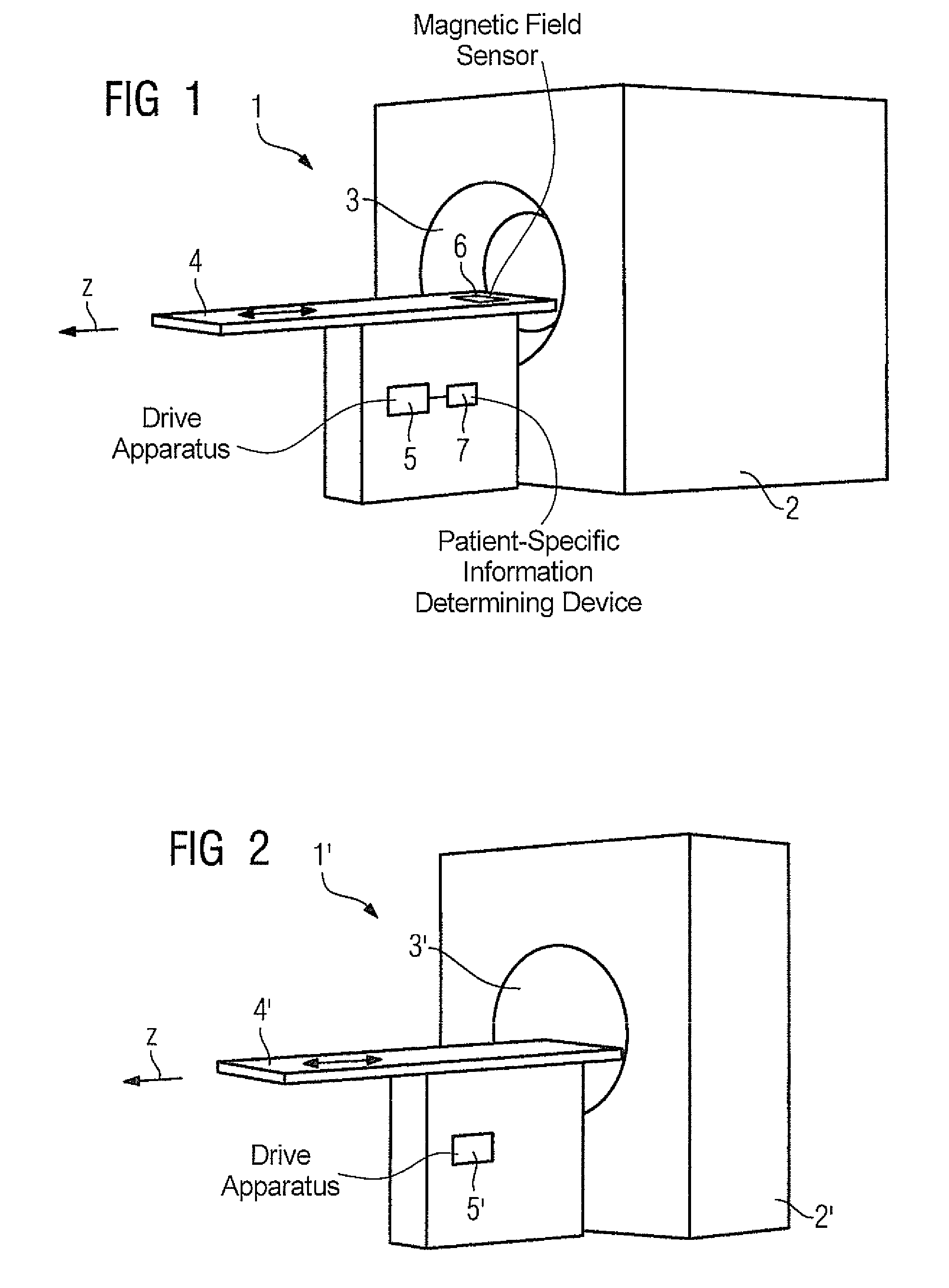
[0030]FIG. 1 shows an inventive magnetic resonance device 1 which is embodied as a whole-body magnetic resonance device. The device 1 includes a magnet arrangement 2, not shown in greater detail, which creates a magnetic field within a patient chamber 3. By means of a patient bed 4 movable along the z-direction, i.e. the direction of movement of the magnetic resonance device 1 a patient can be introduced into the patient chamber 3 and removed from it once again. The patient bed 4 is able to be moved automatically via a drive apparatus 5 which also determines the speed of the patient bed 4.

[0031]In this case the drive apparatus 5 is embodied to move the patient bed 4 at a speed determined as a function of the field distribution of the magnetic field in the direction of movement of the patient bed. In addition to conventional mechanical components, the drive apparatus 5 includes one or more control components that operate the mechanical components in accordance with the invention. At ...


PUM


Abstract

A magnetic resonance device has a patient bed able to be automatically moved by means of a drive apparatus into a patient chamber, as well as a magnet arrangement for creating a magnetic field in the interior of the patient chamber. The drive apparatus is operated so as to move the patient bed at a speed determined as a function of the distribution of the magnetic field in the direction of movement of the patient bed.

Description

BACKGROUND OF THE INVENTION[0001]1. Field of the Invention[0002]The invention relates to a magnetic resonance device of the type having a patient bed able to be moved into a patient chamber automatically by means of a drive apparatus, as well as a magnet arrangement for creating a magnetic field within the patient chamber.[0003]2. Description of the Prior Art[0004]Magnetic resonance devices of the above type for obtaining magnetic resonance images are widely known. Since the patient chamber frequently has quite a small diameter, the patient is placed on the patient bed outside the patient chamber, after which the patient bed can be automatically moved into the patient chamber by means of the drive apparatus.[0005]With the advent of high-field magnetic resonance devices, for example with fields of up to 7T, patients have been reporting side-effects when they are introduced into the patient chamber. These side effects manifest themselves, for example, in the form of a feeling of dizzi...

Claims


Application Information

Patent Timeline
Patent Type & Authority Patents(United States)
IPC IPC(8): A61B5/055
CPCA61B5/0555G01R33/307G01R33/288A61B5/055
Inventor SCHMITT, FRANZ
Owner SIEMENS HEALTHCARE GMBH
Why Eureka
Try Eureka