Perpendicular magnetic recording head laminated with AFM-FM phase change material

a phase change material and magnetic recording head technology, applied in the field of pmr main pole layer of pmr writer, can solve the problems loss of writability (write field), and loss of data erasure in the magnetic medium during non-write operations, so as to reduce remanence, minimize pole erasure, and strong write field

Inactive Publication Date: 2011-08-23
HEADWAY TECH INC
View PDF25 Cites 30 Cited by
  • Summary
  • Abstract
  • Description
  • Claims
  • Application Information

AI Technical Summary

Benefits of technology

[0016]One objective of the present invention is to provide a laminated main pole layer that reduces remanence during non-write operations to minimize pole erasure, and has a strong write field comparable to single pole writers to achieve high writability.
[0017]Another objective of the present invention is to provide a flux gate in the main pole layer to reduce remanent flux leaking from the yoke into the write pole tip and thereby minimizing pole erasure caused by yoke remanence.
[0023]In a fifth embodiment, the PMR head from a cross-track view has at least a portion of the yoke and the entire write pole made of a single ferromagnetic layer. Between the write pole and the yoke is an AFM-FM phase change material layer that serves as a flux gate to prevent remanence flux leaking from the yoke into the write pole. In one aspect, only the flare portion of the main pole layer is made of the AFM-FM phase change material. However, the present invention also encompasses an embodiment in which the flare portion and a section of the yoke that adjoins the flare portion are made of an AFM-FM phase change material. As mentioned previously, AFM-FM transition is achieved by heating / cooling from the write coils at writing / non-writing conditions or by thermal heating / cooling realized with a separate electrical path that heats locally on the laminated portion of the write head with electrical current.
[0024]In a sixth embodiment, the main pole layer has a stitched structure in which the yoke portion and a first section of the flare portion form a single ferromagnetic layer. A second section of the flare portion and the write pole have the same thickness and width and are comprised of an AFM-FM phase change material layer and a ferromagnetic layer. One side of the AFM-FM phase change material layer in the second section adjoins a side of the first section of the flare portion, and a side of the AFM-FM phase change material layer opposite the first section adjoins the single ferromagnetic layer in the write pole and second section of the flare portion. The AFM-FM phase change material layer may serve as a flux gate to prevent remanent flux from the yoke and first section of the flare portion from reaching the write pole tip.

Problems solved by technology

However, prior studies have shown that the perpendicular direction shape anisotropy in the smaller writer pole tips may lead to serious pole erasure (PE).
In other words, a remanent magnetic field can exist in the write pole tip after the write current is turned off thereby leading to data erasure in the magnetic medium during non-write operations.
Unfortunately, reducing the PE field with either magneto-static coupling or AFM coupling results in a loss in writability (write field) and particularly near the trailing edge of the write pole tip.
However, the high anisotropy also makes the magnetization in the recording layer not easy to reverse during a write process.
This process which generally results in a bcc CsCl type FeRh crystalline structure is considered too harsh for commercial recording head fabrication.
One disadvantage of prior art AFC lamination schemes is that the coupling strength of a FeCo / Ru / FeCo configuration or the like is typically large and this type of AFC lamination will inevitably cause a large anisotropy field and low magnetic moment under a low field.

Method used


Image

  • Perpendicular magnetic recording head laminated with AFM-FM phase change material
  • Perpendicular magnetic recording head laminated with AFM-FM phase change material
  • Perpendicular magnetic recording head laminated with AFM-FM phase change material

Examples


first embodiment

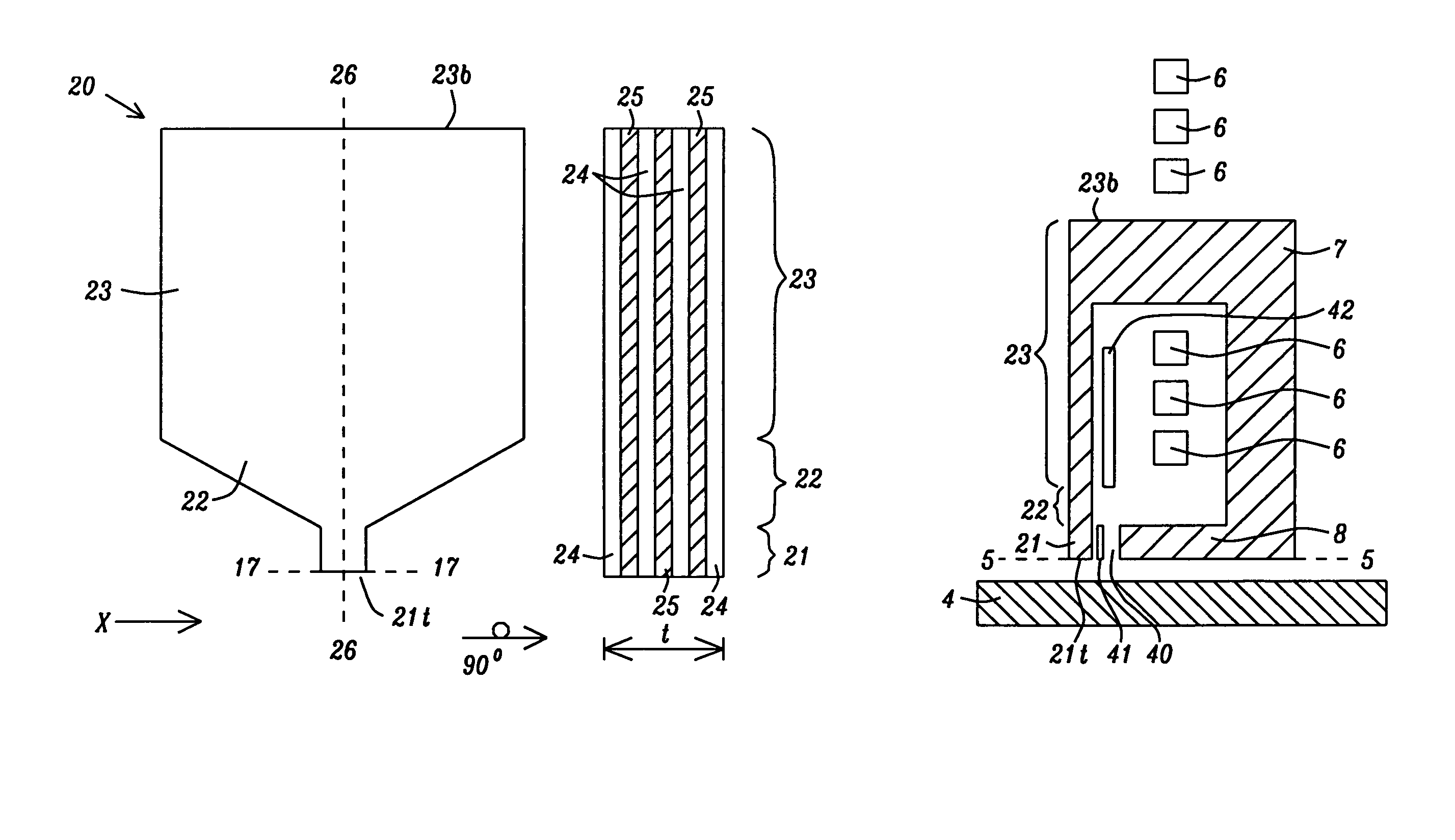
[0049]Referring to FIG. 6a, the present invention is illustrated with a down-track view of a PMR write head 20 on the left and a cross-track view on the right. The cross-track view is obtained by rotating the down-track view 90 degrees into the plane of the paper along the axis 26-26. The PMR writer is comprised of a write pole 21 having a write pole tip 21t formed along the ABS (not shown), a flare portion 22 of a main pole layer that adjoins a side of the write pole opposite the ABS, and a yoke 23 that adjoins the flare portion along a side (not shown) opposite the write pole. In other words, the flare portion approximates a triangular shape, and the yoke may have a rectangular or square shape as viewed from a down-track position. The yoke 23 concentrates the magnetic flux and serves as a conduction path of the magnetic field generated by the writer coils (not shown) on one or both sides of the yoke. The flare portion 22 usually serves to further concentrate the flux from the yoke...

third embodiment

[0053]Referring to FIG. 8, a third embodiment is shown with a down-track view (left) and cross-track view (right) wherein the PMR writer 20 is partially laminated. In particular, the yoke 23 is comprised entirely of a single ferromagnetic layer 30 that may be made of the same magnetic material as in ferromagnetic layers 24. In addition, the ferromagnetic layer 30 extends into the flare portion and stops at a plane 29-29 that is a distance c of about 0 to 10 microns from the end of the write pole 21 that is opposite the ABS 17-17. When c>0, the write pole 21 and a section of the flare portion 22 adjacent to the write pole are made of a laminated structure comprised of alternating ferromagnetic layers 24 and AFM-FM phase change material layers 25 as described in the first two embodiments. The ferromagnetic layer 30 has a thickness t in the x-axis direction along a plane that is parallel to the ABS 17-17, and the laminated structure in the write pole and adjacent section of the flare p...

fifth embodiment

[0060]Referring to FIG. 11, the present invention also encompasses a fifth embodiment in which an AFM-FM phase change material layer 25a is employed as a flux gate to prevent flux leakage from the yoke 23 to the write pole 21. In an AFM phase during a non-writing condition, the flux gate has close to air magnetic permeability such that the write pole 21 and yoke 23 are essentially magnetically separated. Therefore, the remanent magnetic flux from the magnetic domains or grains in the yoke 23 are prevented from influencing the write pole tip 21t and the PE field can be substantially reduced in a non-writing condition. Besides reducing magnetic remanence from the yoke 23, the flux gate while in an AFM phase also decreases the external field being conducted by the yoke and concentrated by the write pole 21 to minimize unwanted erasure. During a write operation, the flux gate is switched to a FM state and acts like a magnetic material with high permeability.

[0061]In one aspect, the AFM-...


PUM

PropertyMeasurementUnit
temperatureaaaaaaaaaa
transition temperatureaaaaaaaaaa
thicknessaaaaaaaaaa

Abstract

A PMR writer is disclosed that minimizes pole erasure during non-writing and maximize write field during writing through an AFM-FM phase change material that is in an AFM state during non-writing and switches to a FM state by heating during writing. The main pole layer including the write pole may be comprised of a laminated structure having a plurality of “n” ferromagnetic layers and “n−1” AFM-FM phase change material layers arranged in an alternating manner. The AFM-FM phase change material is preferably a FeRh or FeRhX alloy (X=Pt, Pd, or Ir) having a Rh content >35 atomic %. AFM-FM phase change material may also be used as a flux gate to prevent yoke flux from leaking into the write pole tip. Heating for the AFM to FM transition is provided by write coils and / or a coil located near the AFM-FM phase change material to enable faster transition times.

Description

FIELD OF THE INVENTION[0001]The invention relates to a main pole layer of a PMR writer and in particular to an antiferromagnetic (AFM)-ferromagnetic (FM) phase change material that may be employed in the write pole tip and / or the yoke to minimize data erasure after a write operation without significantly reducing the write field during a write operation.BACKGROUND OF THE INVENTION[0002]Perpendicular magnetic recording (PMR) has become the mainstream technology for disk drive applications beyond 200 Gbit / in2, replacing longitudinal magnetic recording (LMR) devices. Due to the continuing reduction of transducer size, high moment soft magnetic thin films with a Bs above 22 kG are required for write head applications. A PMR head which combines the features of a single pole writer and a double layered media has a great advantage over LMR in providing higher write field, better read back signal, and potentially much higher areal density. In particular, a shielded pole head can provide a l...

Claims


Application Information

Patent Timeline
Patent Type & Authority Patents(United States)
IPC IPC(8): G11B5/127G11B5/147
CPCG11B5/1278G11B5/147G11B5/3113G11B5/3146Y10T29/49034Y10T29/49044Y10T29/49032Y10T29/49043
Inventor ZHOU, YUCHENTAKANO, KENICHILIU, KOWANGZHANG, KUNLIANGGUAN, LIEJIEDOVEK, MORISSMYTH, JOE
Owner HEADWAY TECH INC
Why Eureka
Try Eureka