Inductor's Electromagnetic Balance Improvement Method

a technology of electromagnetic balance and inductors, applied in the direction of transformers/inductors/coils/windings/connections, inductances, instruments, etc., can solve the problems of inability of existing inductors to meet international circuit indicator requirements, inability to stabilize components of circuit boards, etc., to improve the electromagnetic balance of inductors, shorten the gap, and reduce remanence

Inactive Publication Date: 2019-12-26
SHENZHEN SIMIDE ELECTRONICS TECH CO LTD
View PDF0 Cites 0 Cited by
  • Summary
  • Abstract
  • Description
  • Claims
  • Application Information

AI Technical Summary

Benefits of technology

[0012]This invention has following advantages as compared with existing technologies:
[0013]This invention proposes an inductor's electromagnetic balance improvement method which equips protective box inside magnet ring with an arc-shaped shield. It can block out electromagnetism of magnet ring from all angles to reduce remanence, improve inductor's electromagnetic balance and shorten the gap between inaction current of fire wire and that of naught wire.

Problems solved by technology

Since toroidal magnetic field faces a lack of balance because of existing inductors' inability to block out electromagnetism of magnet ring, there will be remanence when electric signal goes through magnet ring.
The remanence can cut magnetic line of magnet ring's coil to result in null piezoelectricity, which may lead to instability of components in circuit board.
Obviously, existing inductors are incapable of meeting international circuit indicator requirements.

Method used


Image

  • Inductor's Electromagnetic Balance Improvement Method
  • Inductor's Electromagnetic Balance Improvement Method

Examples


example 2

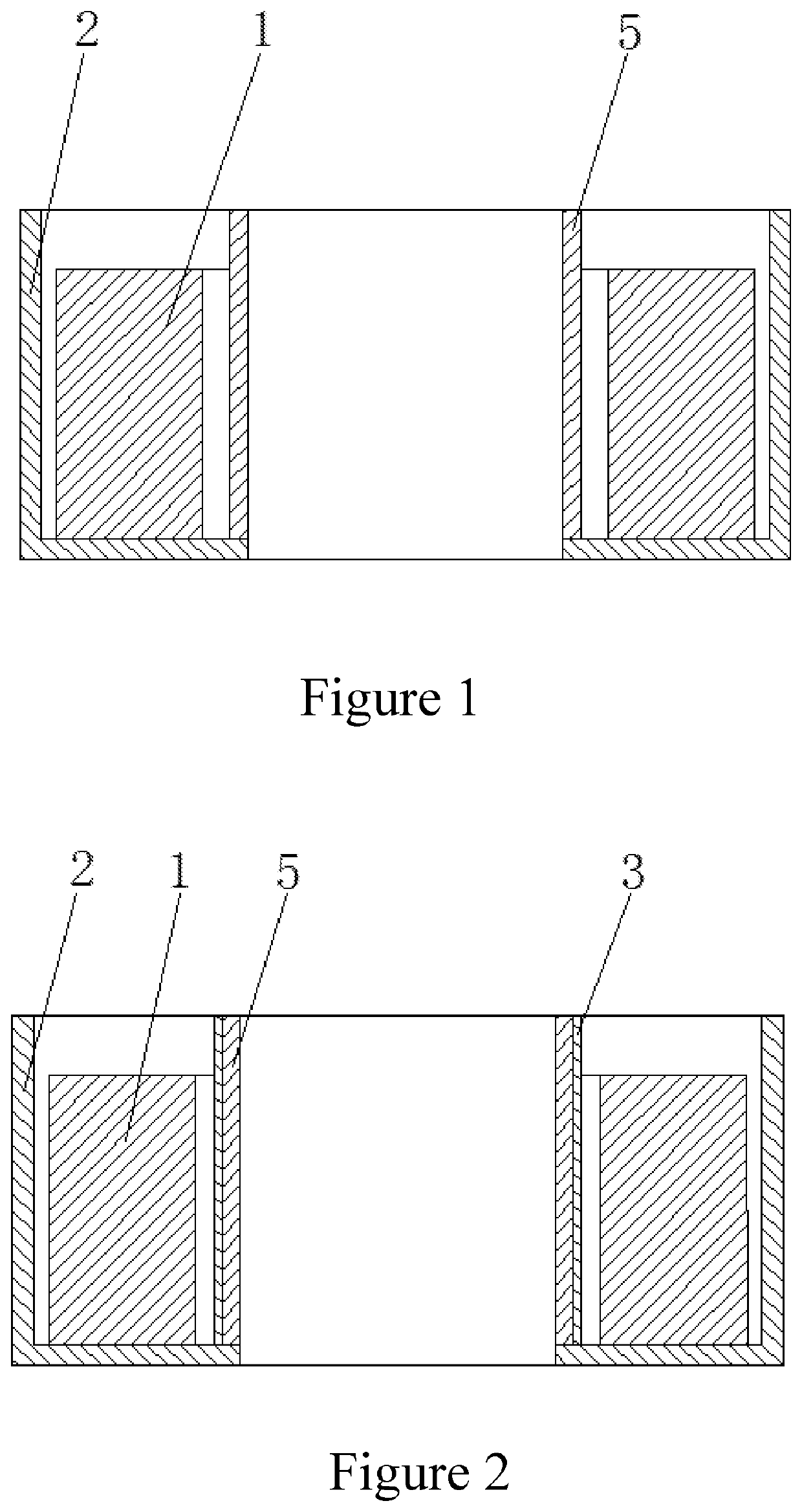
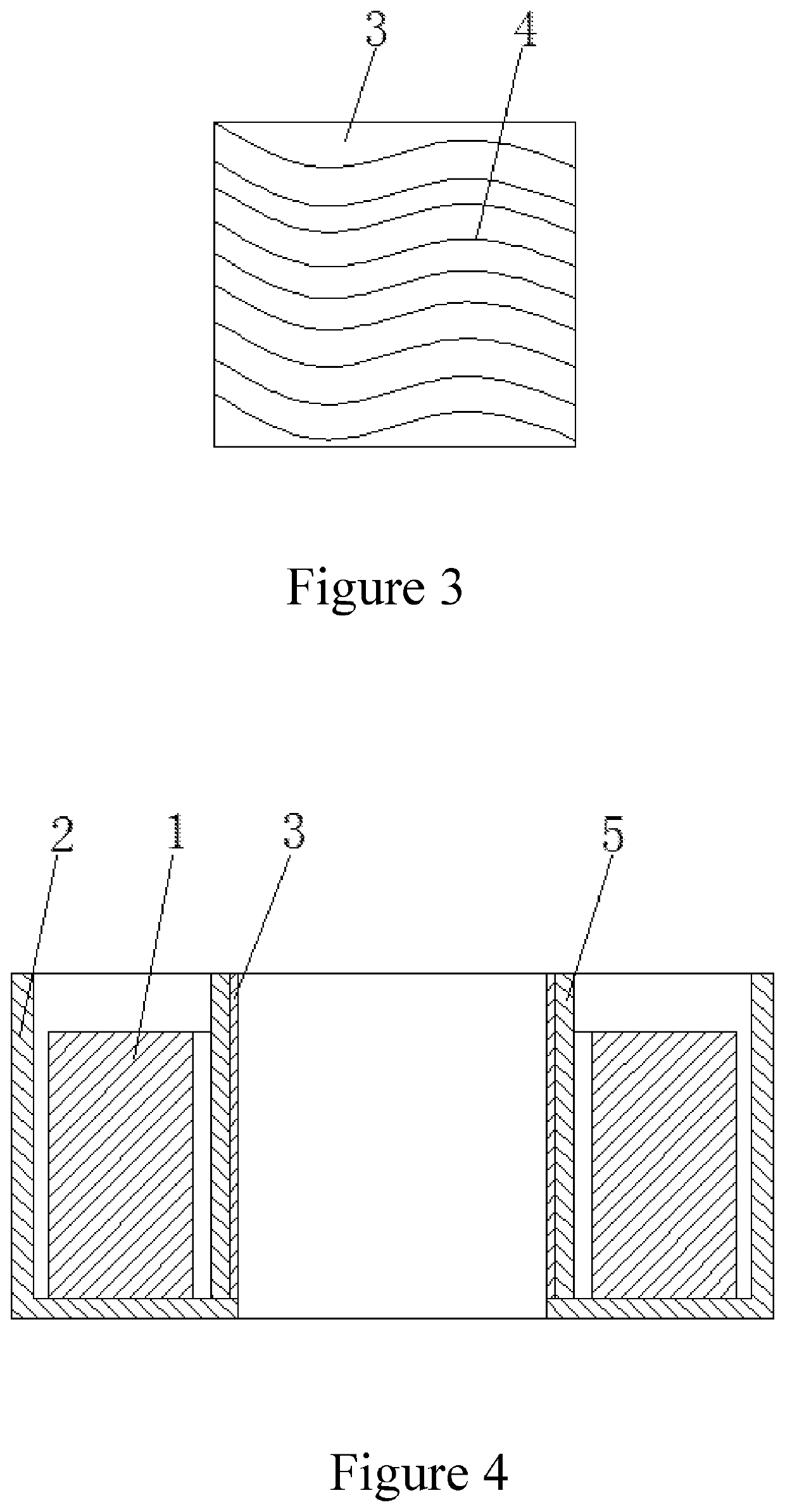
[0023]FIG. 4 provides another example of this invention, which installs shield 3 in the inner wall of locating seat 5 in protective box 2. Shield 3 can be embedded in the inner wall of locating seat 5 to constitute a whole with protective box 2. At the same time, it can be wrapped in fire wire and naught wire, and then installed in the inner wall of locating seat 5 in protective box with them. This can reduce assembly and installation steps of shield 3 to greatly improve production efficiency and decrease labor intensity.

[0024]All above are the preferable implementation modes in this invention. It is worth noticing that on the premise of adopting structure of this invention, any changes or improvements made by technicians in this field shall not affect the implementation results of this invention and patent's practicality.


PUM

PropertyMeasurementUnit
current gapsaaaaaaaaaa
electromagneticaaaaaaaaaa

Abstract

This invention proposes an inductor's electromagnetic balance improvement method which equips protective box inside magnet ring with an arc-shaped shield. It can block out electromagnetism of magnet ring from all angles to reduce remanence, improve inductor's electromagnetic balance, and shorten the gap between action current of fire wire and that of naught wire. In this way, product yield rate can be increased.

Description

TECHNICAL FIELD[0001]To be specific, this invention refers to an inductor's electromagnetic balance improvement method in the technical field of inductor manufacturing.TECHNICAL BACKGROUND[0002]Now, electric appliances of new energy vehicles such as charging pile and instrument circuit tend to be equipped with mutual inductors like zero-sequence mutual inductor, common-mode inductor and differential-mode inductor. As shown by FIG. 1, magnet ring 1 made of electromagnetic material is sleeved in locating seat 5 in protective box 2. Since toroidal magnetic field faces a lack of balance because of existing inductors' inability to block out electromagnetism of magnet ring, there will be remanence when electric signal goes through magnet ring. The remanence can cut magnetic line of magnet ring's coil to result in null piezoelectricity, which may lead to instability of components in circuit board. For example, since earth leakage circuit breaker is intended to control grid power safety, an...

Claims


Application Information

Patent Timeline
Patent Type & Authority Applications(United States)
IPC IPC(8): H01F27/36H01F41/02H01F27/02H01F27/28
CPCH01F41/02H01F27/28H01F27/36H01F27/02H01F38/20H01F27/366H01F17/062H01F27/266G01R15/183
Inventor CHEN, GUANG-JINTAN, BAO-LIANG
Owner SHENZHEN SIMIDE ELECTRONICS TECH CO LTD
Why Eureka
Try Eureka