Sprinkler with dual shafts

a sprinkler and shaft technology, applied in the direction of spraying nozzles, movable spraying apparatus, spraying apparatus, etc., can solve the problems of difficult control of the speed of rotation of the deflector plate, difficult adjustment of the watering arc and watering radius settings of the rotating stream sprinkler, etc., to overcome the clutch. clutch restriction, increase the opening of the flow passag

Active Publication Date: 2011-08-30
TORO CO THE
View PDF32 Cites 38 Cited by
  • Summary
  • Abstract
  • Description
  • Claims
  • Application Information

AI Technical Summary

Benefits of technology

In a preferred embodiment of the present invention a sprinkler is provided, having a first shaft coupled to a drive mechanism and a grooved deflector. A second shaft is disposed within the first shaft, coupled to a water flow adjustment mechanism and an adjustment region on the top of the deflector. The first shaft transfers rotational movement from the drive mechanism to a grooved deflector on the top of the sprinkler. The second shaft rotates with the first shaft during normal operation due to a friction clutch within the sprinkler. When the user desires to adjust the water flow (i.e., the radius of the water), the friction of the clutch can be overcome by rotating the second shaft, increasing openings of flow passages within the sprinkler body. In this respect, flow adjustments can be made from the top of the sprinkler while the deflector rotates.

Problems solved by technology

Due to their often small size, the watering arc and watering radius settings of the rotating stream sprinklers can be difficult to adjust.
Further, the rotatable deflectors of most prior art rotating stream sprinklers are driven by the force of water striking angled surfaces on the deflector.
Hence, it can be difficult to control the speed of rotation of the deflector plate.

Method used


Image

  • Sprinkler with dual shafts
  • Sprinkler with dual shafts
  • Sprinkler with dual shafts

Examples


Embodiment Construction

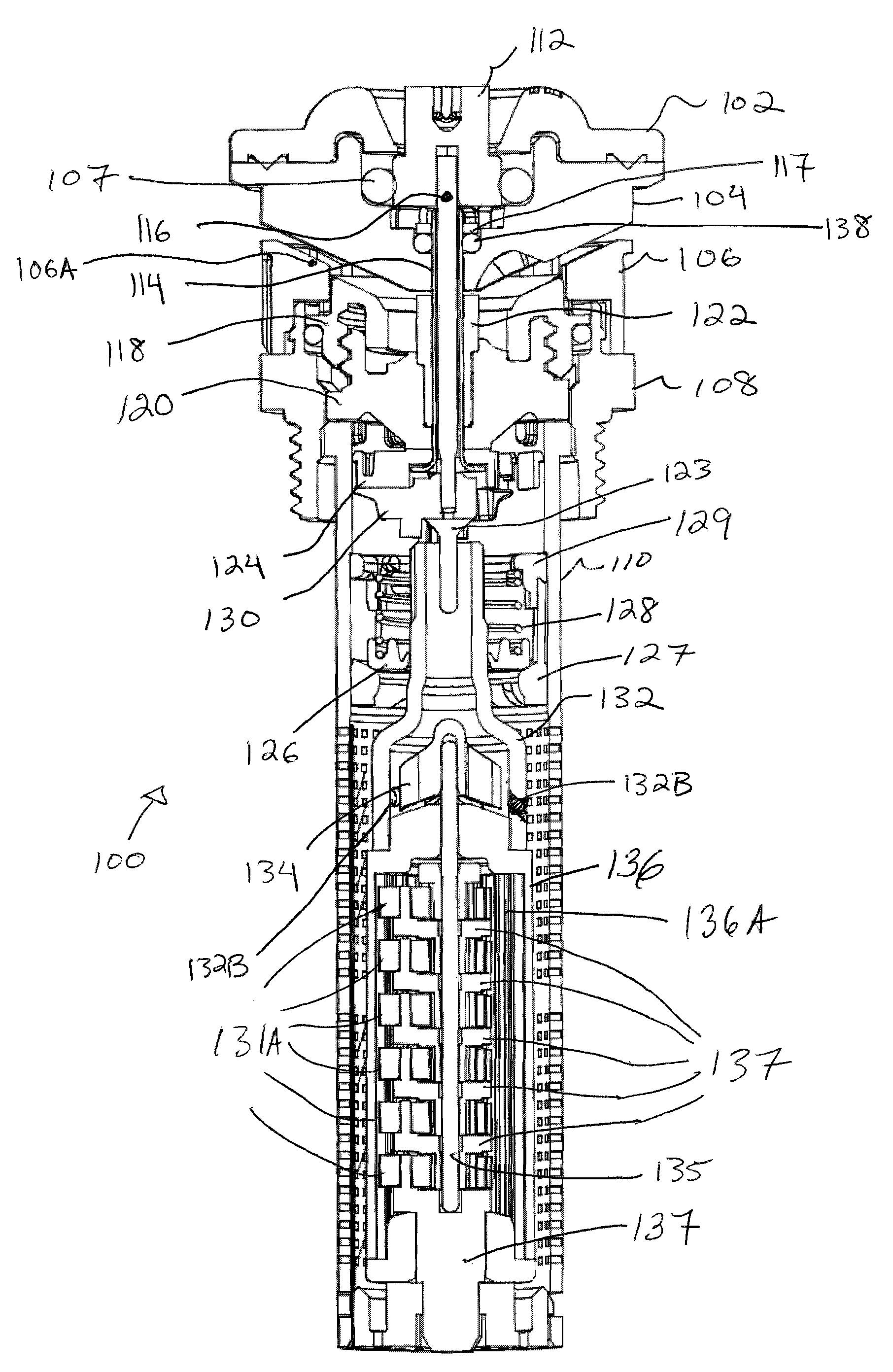
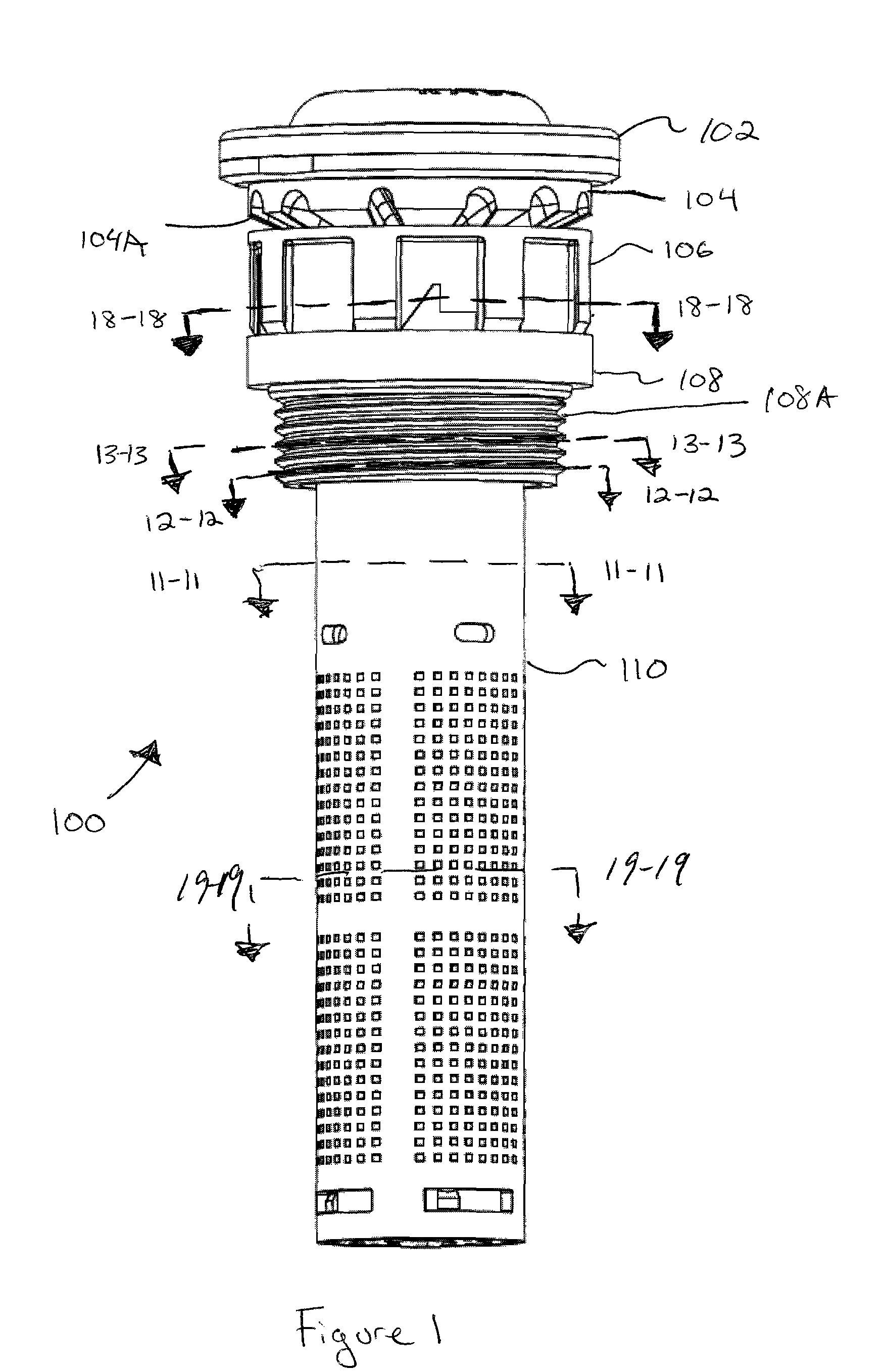
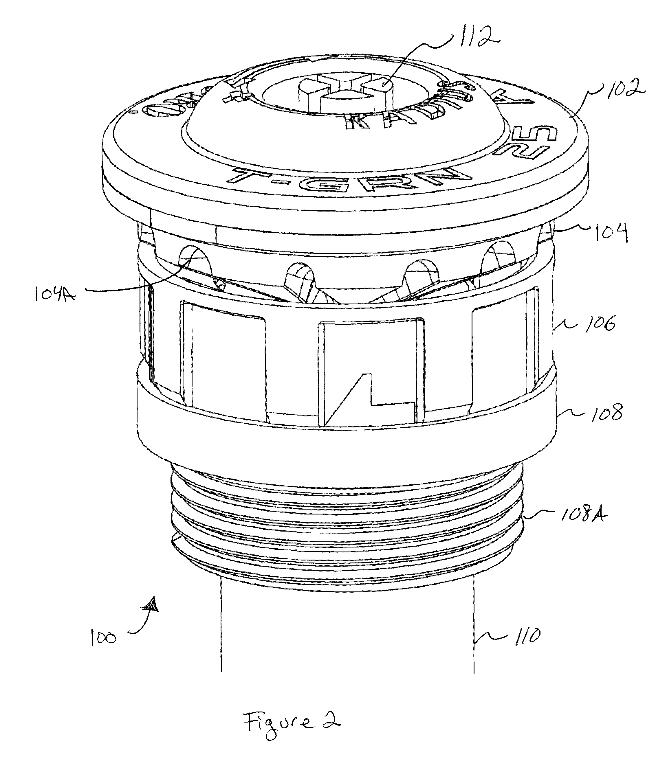
FIGS. 1 and 2 illustrate a rotating stream sprinkler 100 according to the present invention. The sprinkler 100 includes a grooved deflector plate 104 that distributes water streams from channels 104A while rotating. The sprinkler arc is adjusted by rotating arc adjustment member 106 and the flow (i.e., the distance or radius of the water flow) is adjusted by rotating the flow adjustment member 112 at the top cover 102. The outer base member 108 includes a thread 108A for screwing into an appropriate sprinkler riser to mount the sprinkler 100. Note that while the thread 108A faces outward from the sprinkler 100 (a male fitting), other thread orientations are possible such as an inwardly facing thread (female fitting).

As seen in the cross sectional views of FIGS. 3-5, the sprinkler 100 includes a drive shaft 114 that drives rotational movement of the deflector plate 104 and a flow adjustment shaft 116 that adjusts the flow adjustment mechanism.

The drive shaft 114 includes a passage ex...


PUM


Abstract

In a preferred embodiment of the present invention a sprinkler is provided, having a first shaft coupled to a drive mechanism and a grooved deflector. A second shaft is disposed within the first shaft, coupled to a water flow adjustment mechanism and an adjustment region on the top of the deflector. The first shaft transfers rotational movement from the drive mechanism to a grooved deflector on the top of the sprinkler. The second shaft rotates with the first shaft during normal operation due to a friction clutch within the sprinkler. When the user desires to adjust the water flow (i.e., the radius of the water), the friction of the clutch can be overcome by rotating the second shaft, increasing openings of flow passages within the sprinkler body. In this respect, flow adjustments can be made from the top of the sprinkler while the deflector rotates.

Description

BACKGROUND OF THE INVENTIONRotating stream sprinklers, also known as mini stream sprinklers, deliver a plurality of rotating streams to the surrounding terrain. The streams are achieved by directing water against a rotatable deflector plate having a plurality of vanes on its lower surface. As the deflector plate rotates, these streams move within a predetermined watering arc set by the user.The plurality of streams that emanate from the sprinkler provide a visually appealing water dispersal. Additionally, the plurality of streams provides greater wind resistance and more uniform distribution to the surrounding turf.Due to their often small size, the watering arc and watering radius settings of the rotating stream sprinklers can be difficult to adjust. Further, the rotatable deflectors of most prior art rotating stream sprinklers are driven by the force of water striking angled surfaces on the deflector. Hence, it can be difficult to control the speed of rotation of the deflector pla...

Claims


Application Information

Patent Timeline
Patent Type & Authority Patents(United States)
IPC IPC(8): B05B3/04
CPCB05B3/0422B05B3/007
Inventor RENQUIST, STEVEN C.JANKU, PETERMCCLURE, RICHARD C.MANANDHAR, SAROJ
Owner TORO CO THE
Why Eureka
Try Eureka