Treadmill speed control system

a control system and treadmill technology, applied in the field of treadmills, can solve the problems of difficult control of the speed of the treadmill, difficulty in maintaining a desired speed, and difficulty in operating and controlling the treadmill, and achieve the effect of cost and weight of the drive motor, and cost of operation

Inactive Publication Date: 2011-08-30
JOHNSON HEALTH TECH
View PDF9 Cites 36 Cited by
  • Summary
  • Abstract
  • Description
  • Claims
  • Application Information

AI Technical Summary

Benefits of technology

A treadmill with a flywheel in accordance with the present invention, can have the flywheel attached to a roller around which the tread is disposed. As the tread moves, the roller turns, causing the flywheel to spin. Inertia from the spinning flywheel helps maintain a consistent speed of the tread.
Alternatively, a flywheel can be located elsewhere, such as in front of the tread, and operatively connected to the tread by a set of pulleys and a belt. One advantage of this configuration is that the set of pulleys may be sized to rotate the flywheel at a faster rate than the roller around which the tread is disposed. By increasing the angular velocity of the flywheel, the size and weight of the flywheel can be reduced, while still maintaining the same rotational inertia. Other flywheel locations could be used to the same effect while remaining within the scope of the invention.
The present invention is directed to a non-motorized treadmill that avoids the previously described disadvantages of motorized treadmills, such as cost and weight of the drive motor, as well as the cost of operation, while having the ability to match the speed of the tread to a target tread speed.

Problems solved by technology

Such treadmills were difficult to operate and control.
Yet even with a flywheel, these treadmills were difficult to use, and the speed of the treadmill was difficult to control.
This addition of an inclined tread eliminated some of the effort required by the operator to get the tread surface moving, but it was still difficult to maintain a desired speed especially if the tread angle was set too low.
Conversely, if the tread angle was set too high, the tread might move faster than desired.
For example, motorized treadmills require the treadmill to be located near an appropriate electrical source, which limits the potential locations where the treadmill can be placed.
The cost of operating and maintaining motorized treadmills is also higher than non-motorized treadmills.
In addition, motorized treadmills typically cost more than non-motorized treadmills because drive motors and motor controllers are relatively expensive and can account for a significant portion of the total cost of the treadmill.
Another disadvantage of motorized treadmills is that the physical size and weight of a drive motor increases the overall size and weight of the treadmill, and may require specialized designs for moving and storage.

Method used


Image

  • Treadmill speed control system
  • Treadmill speed control system
  • Treadmill speed control system

Examples


Embodiment Construction

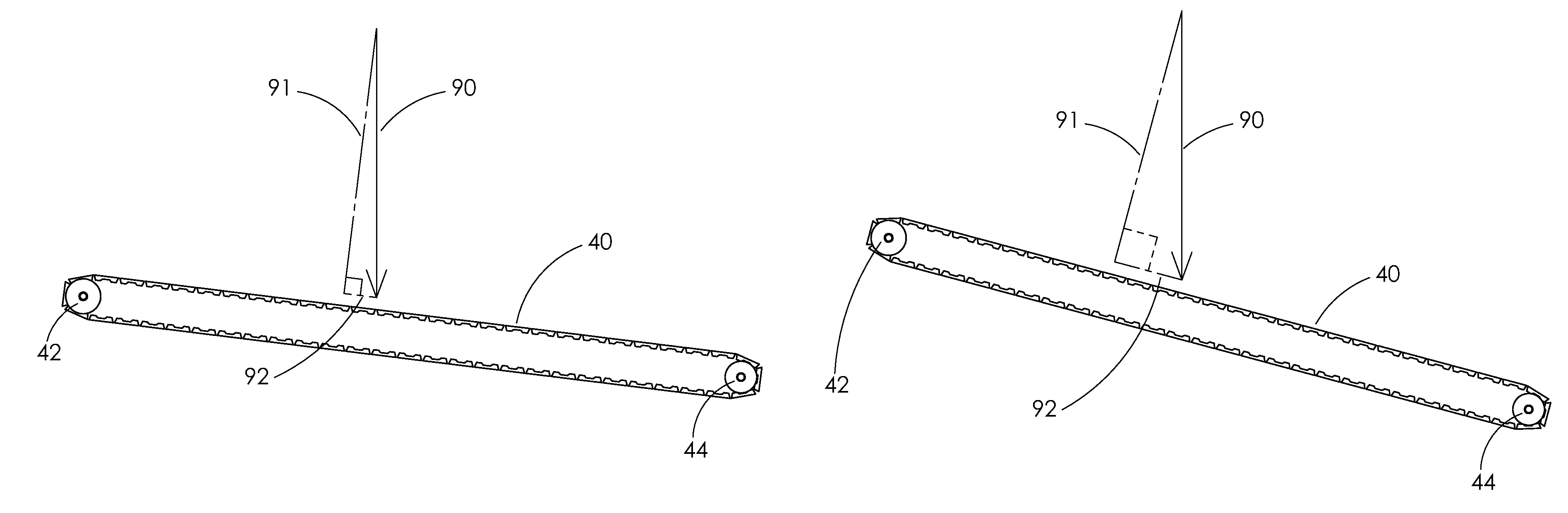
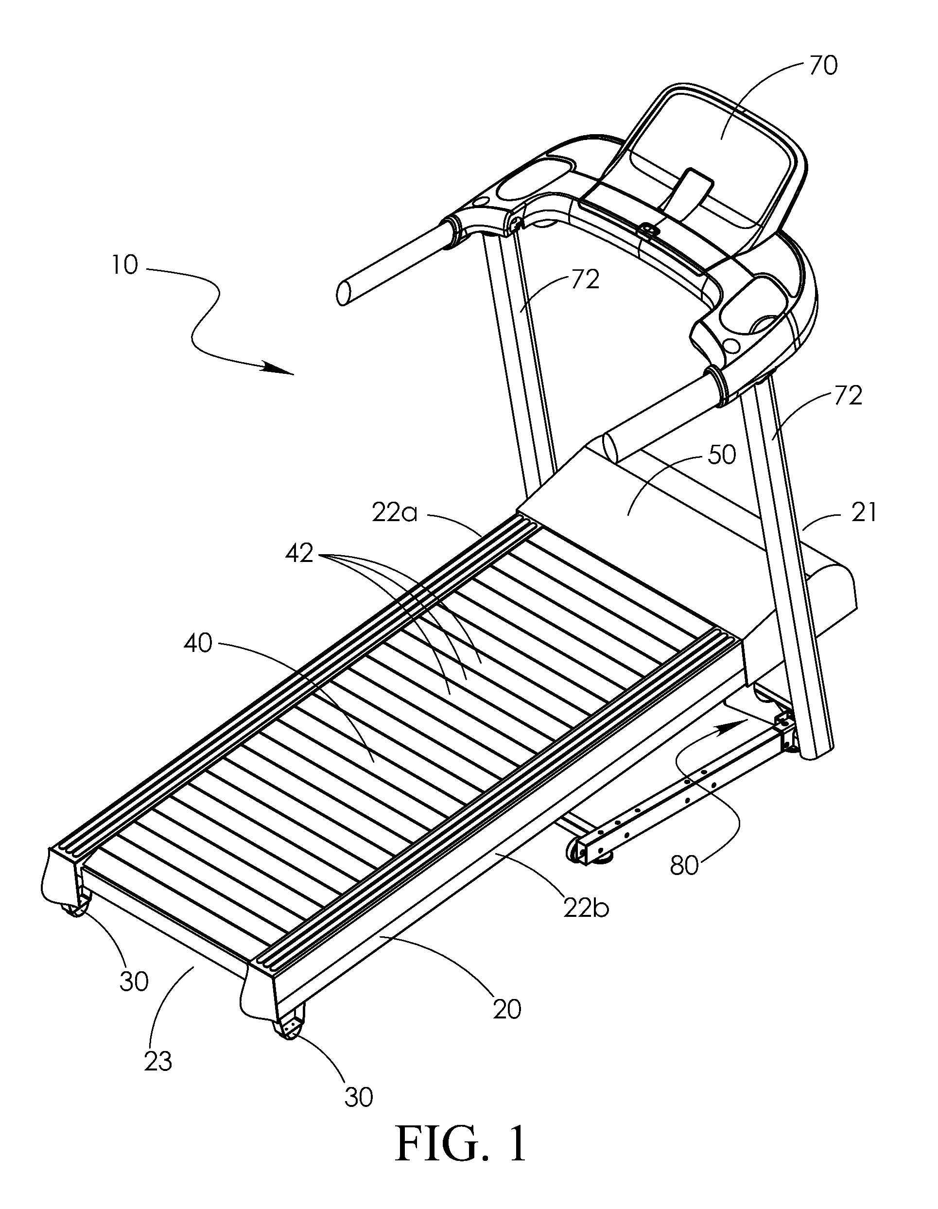
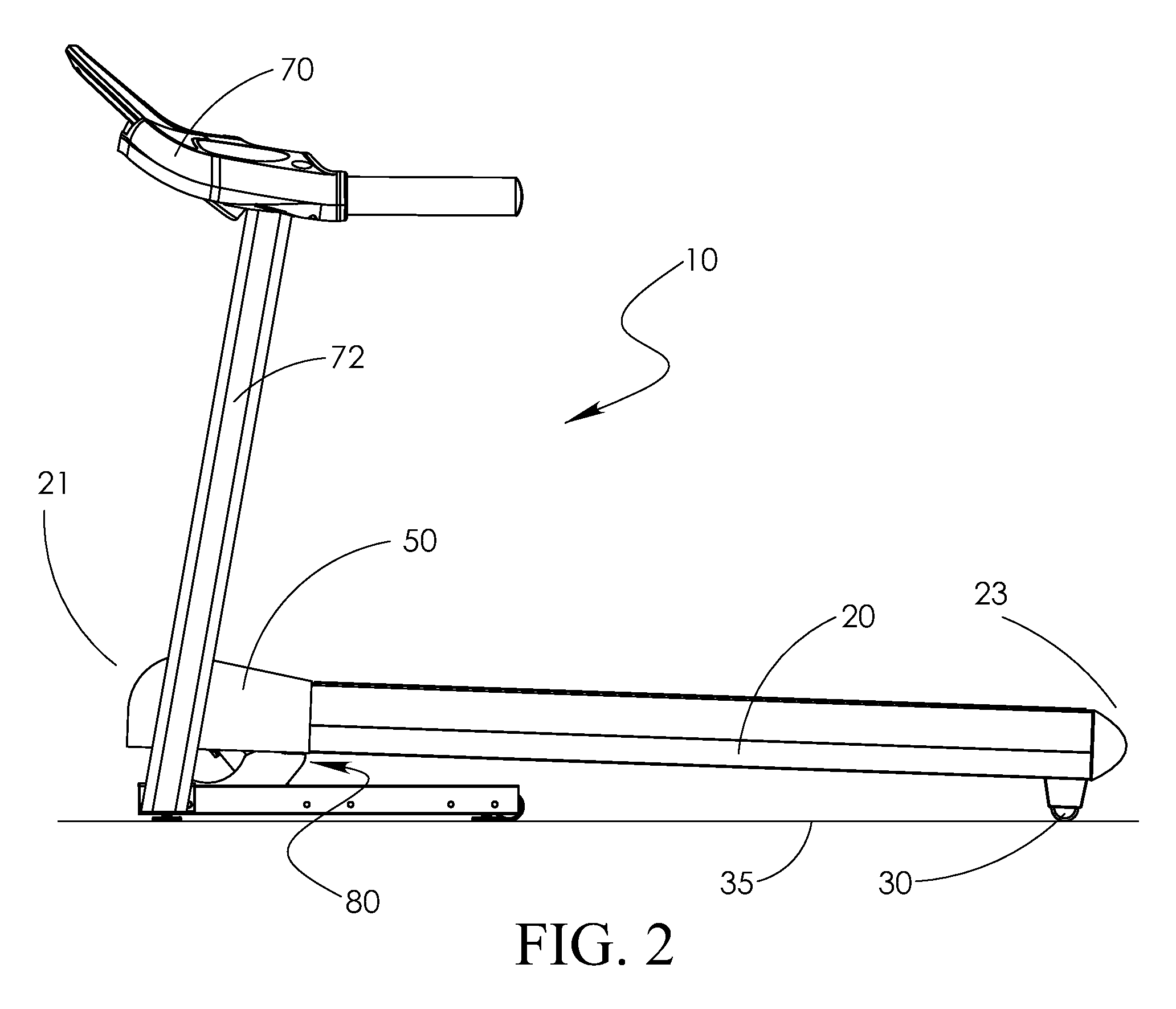
FIG. 1 shows a treadmill 10 of the present invention including a frame 20, a tread 40, and an angle adjustment mechanism 80. The frame 20 includes a front end 21, a pair of side frame members 22a, 22b, and a rear end 23. The treadmill 10 also includes a pair of feet 30, a compartment cover 50, a console 70, and a pair of masts 72 for supporting the console 70.

The frame 20 supports the tread, 40, and the two side frame members 22a, 22b are arranged parallel to one another and are joined by at least one cross member (not shown) to maintain the two side frame members 22a, 22b in position with respect to one another. The frame 20 in the illustrated embodiment includes upright masts 72 supporting the console 70, but the masts 72, when used, are not required to be attached to the frame 20. The frame 20 preferably includes the feet 30 for leveling and / or for supporting the treadmill 10 on the ground, floor or other support surface 35.

The tread 40 is operatively mounted on the frame 20 such...


PUM


Abstract

A treadmill apparatus having a non-motorized tread, a sensor for sensing a parameter indicative of the tread speed, and a controller operatively connected to an angle adjustment mechanism to increase and decrease the angle of the tread. During operation of the treadmill, the controller compares the speed of the tread to a target speed, and based on the comparison, adjust the angle of the tread so that the operator's weight will adjust the speed of the tread.

Description

FIELD AND BACKGROUND OF THE INVENTIONThe present invention relates to a treadmill with a non-motorized tread, as well as methods to set and control the speed of the tread.Exercise treadmills are widely used for walking or running aerobic-type exercise while the operator remains in a relatively stationary position. Exercise treadmills typically have a tread, which is an endless running surface extending between and movable around two substantially parallel and spaced apart rollers. The tread may be made of a belt of a rubber-like material, or alternatively, the tread may be made of a number of slats positioned substantially parallel to one another and attached to one or more bands which extend around the rollers.Early treadmills had non-motorized treads that required the operator to provide all of the force necessary to drive and control the speed of the tread by walking or running on the tread surface. Such treadmills were difficult to operate and control. To help control tread spee...

Claims


Application Information

Patent Timeline
Patent Type & Authority Patents(United States)
IPC IPC(8): A63B22/02A63B71/00A63B21/005
CPCA63B22/0023A63B22/0242A63B21/0053A63B21/015A63B2021/0055A63B2022/025A63B2024/0068A63B2024/0093A63B2220/36A63B22/025A63B21/0055
Inventor MORAN, THOMAS HPYLES, NATHAN
Owner JOHNSON HEALTH TECH
Why Eureka
Try Eureka