Tool and method for implanting an annuloplasty prosthesis

a technology for removing prostheses and tools, applied in the field of surgical tools and methods of implantation, can solve the problems of large inventories of sizers and holders, sutures can become entangled, and the process can be time-consuming, so as to achieve convenient and efficient releasing of the prosthesis.

Active Publication Date: 2011-08-30
MEDTRONIC INC
View PDF96 Cites 1 Cited by
  • Summary
  • Abstract
  • Description
  • Claims
  • Application Information

AI Technical Summary

Benefits of technology

[0010]In one aspect, the present invention generally is directed toward a simplified and more easily employed tool for holding an implantable annuloplasty prosthesis during passage of sutures through the prosthesis and for conveniently and efficiently releasing the prosthesis from the tool. Separation of the implantable prosthesis and the tool may be conveniently accomplished without requiring the use of a sharp instrument. Attachment between the prosthesis and the surgical carrying tool can be accomplished in a suture-less fashion.
[0012]In another aspect, the present invention generally is directed toward a method of repairing a heart valve by implanting an annuloplasty prosthesis. The method is characterized by the absence of a need to employ a sharp instrument to effectuate release of the annuloplasty device from a tool otherwise maintaining the annuloplasty device during a portion of the implantation procedure.

Problems solved by technology

This process can be time consuming and requires large inventories of both sizers and holders.
Unfortunately, the sutures can become entangled and it is sometimes difficult to identify corresponding segments of a suture pair.
While accepted, this has the disadvantage of requiring the use of a sharp instrument in close proximity to sensitive anatomical structures and in even closer proximity to the prosthetic repair device which typically has a fabric cover that can otherwise be relatively easily severed.
Further, known annuloplasty device holder designs give rise to the potential of improperly separating the device-retaining suture(s) in more than one location.
This may increase the chance that a stray piece of the cut suture(s) may remain in the patient's body.
Unfortunately, the instruments used in connection with implantation of the annuloplasty prosthesis are cumbersome.

Method used


Image

  • Tool and method for implanting an annuloplasty prosthesis
  • Tool and method for implanting an annuloplasty prosthesis
  • Tool and method for implanting an annuloplasty prosthesis

Examples


Embodiment Construction

[0032]Tool 20

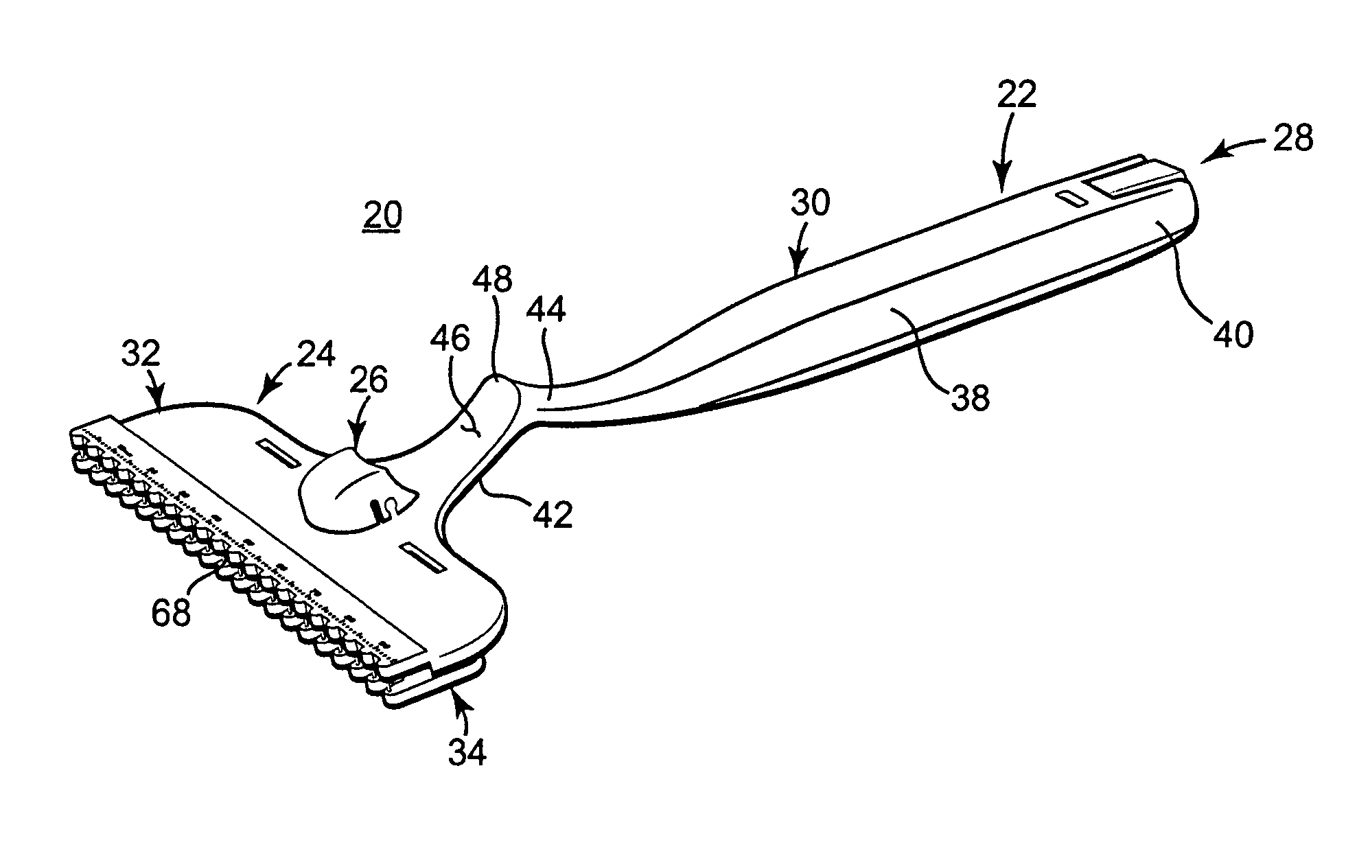
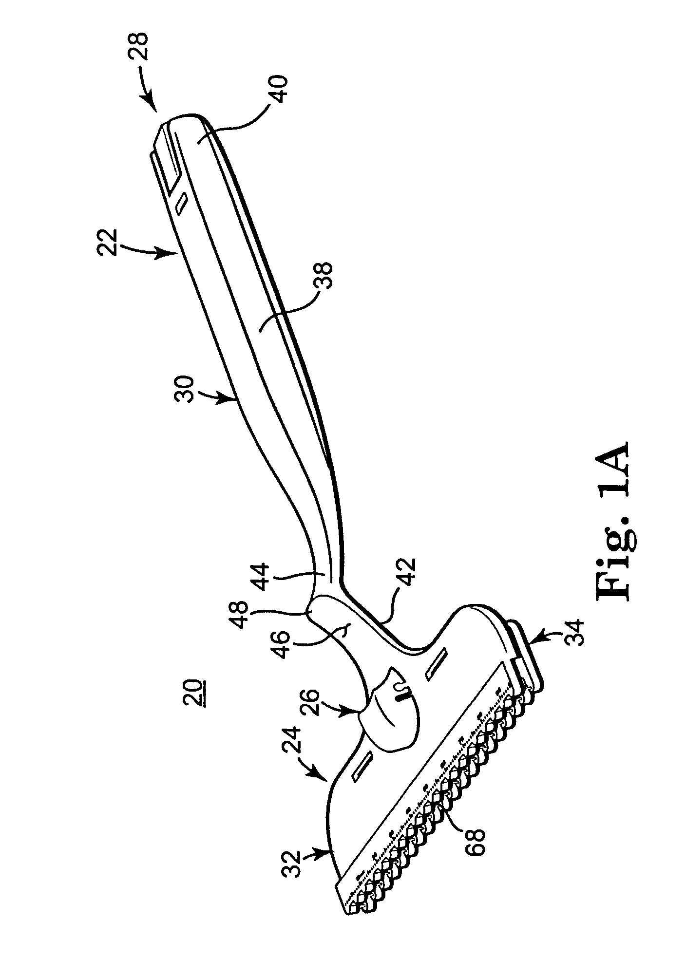
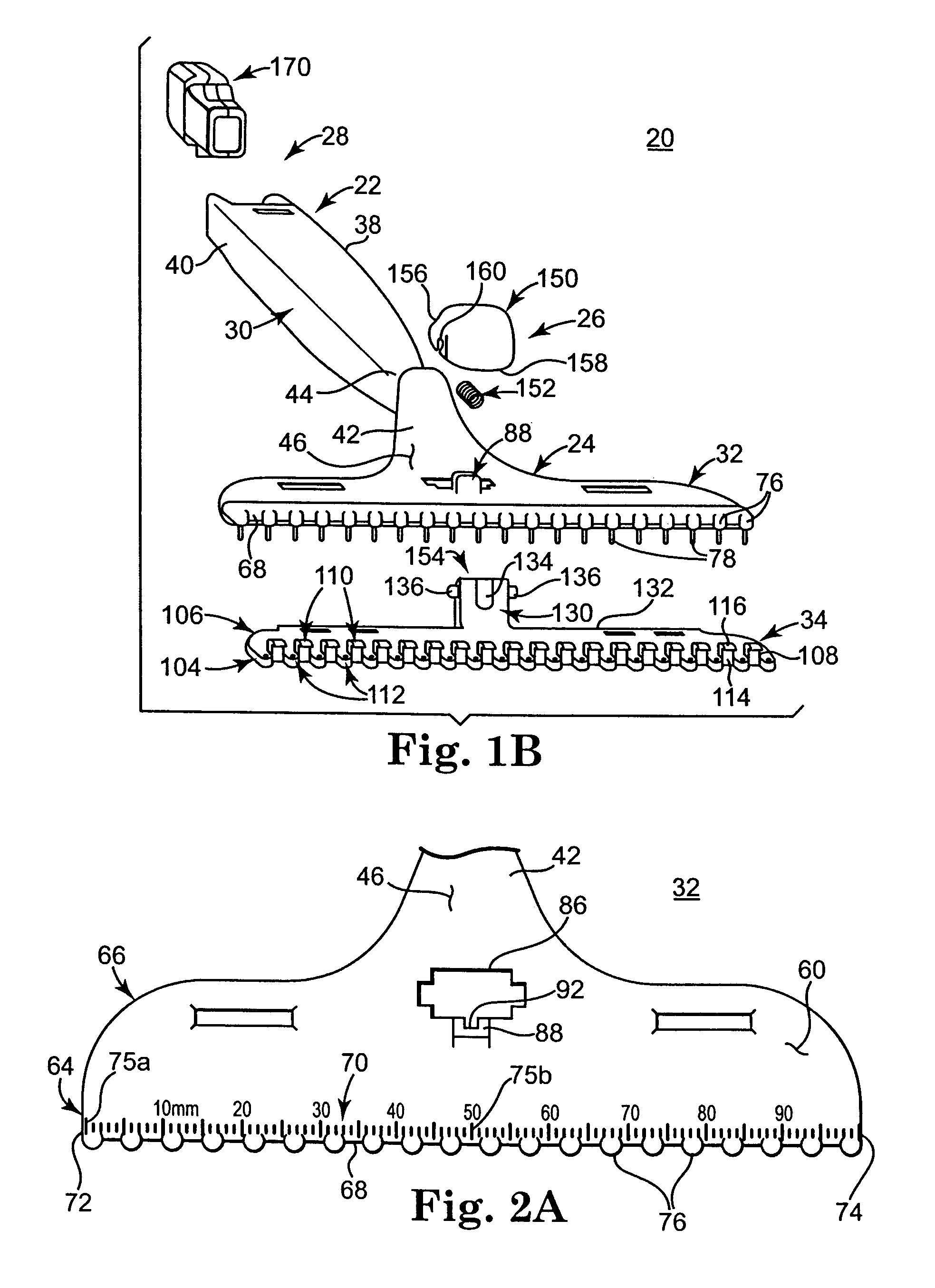
[0033]One embodiment of a tool 20 for use in implanting an annuloplasty prosthesis (not shown) such as an annuloplasty band or ring is shown in FIGS. 1A and 1B. The tool 20 includes an elongate proximal portion 22, a distal portion 24, an actuator mechanism 26 (referenced generally), and a suture management device 28. Details on the various components are provided below. In general terms, however, the proximal portion 22 defines a handle 30 that is sized and shaped to be manually grasped by a single hand of a user. The distal portion 24 includes first and second jaws 32, 34 mounted for relative movement between i) an open state in which the jaws 32, 34 are spaced apart to receive or release an implantable annuloplasty prosthetic, and ii) a closed state (shown in FIG. 1A) in which the first and second jaws 32, 34 are spaced closer together than in the open state. The actuator mechanism 26 facilitates movement of the jaws 32, 34 between the open and closed states. With th...


PUM


Abstract

A simplified and more easily employed tool for holding an implantable annuloplasty prosthesis during passage of sutures through the prosthesis and for conveniently and efficiently releasing the prosthesis from the tool. Separation of the implantable prosthesis and the tool may be conveniently accomplished without requiring the use of a sharp instrument. Attachment between the prosthesis and its surgical carrying tool can be accomplished in a suture-less fashion. The tool includes a suture management device in some embodiments for selectively receiving and maintaining sutures otherwise securing the prosthesis to tissue.

Description

CROSS-REFERENCE TO RELATED APPLICATIONS[0001]This application claims the benefit under §119(e)(1), and incorporates herein by reference an entirety of, U.S. Provisional Application No. 60 / 722,525, filed Sep. 30, 2005 and entitled “Tool and Method for Implanting an Annuloplasty Prosthesis.”BACKGROUND OF THE INVENTION[0002]The present invention relates generally to surgical tools and methods of implantation. More particularly, it relates to surgical tools and methods used in conjunction with heart repair procedures, including tools for holding prostheses such as annuloplasty rings or bands.[0003]Improvements in cardiopulmonary bypass and myocardial protection and standardization of surgical techniques have lead to increasing interest in valve reconstruction procedures. See, for example, Ormiston J A, Shah P M, Tei C, et al., Size and Motion in the Mitral Valve Annulus in Man, Circulation 1981; 64:113; Dagum P, Green G R, Glasson J R, et al., Potential Mechanism of Left Ventricular Out...

Claims


Application Information

Patent Timeline
Patent Type & Authority Patents(United States)
IPC IPC(8): A61F2/24A61B17/00
CPCA61B17/0469A61B17/0483A61B17/06061A61F2/2448A61F2/2466A61B17/0467A61B2017/0472A61B2017/0496A61B2019/446A61B2019/461A61B90/94A61B2090/061
Inventor RYAN, TIMOTHY R.TABOR, CHARLES P.
Owner MEDTRONIC INC
Why Eureka
Try Eureka