Electrically-driven dump truck
a dump truck and electric motor technology, applied in the direction of engine-driven generators, motor/generator/converter stoppers, process and machine control, etc., can solve the problems of increasing the noise level inside the cab, and increasing the size of resistor boxes. , to achieve the effect of easy propagation, increased noise level inside the cab, and large siz
- Summary
- Abstract
- Description
- Claims
- Application Information
AI Technical Summary
Benefits of technology
Problems solved by technology
Method used
Image
Examples
first embodiment
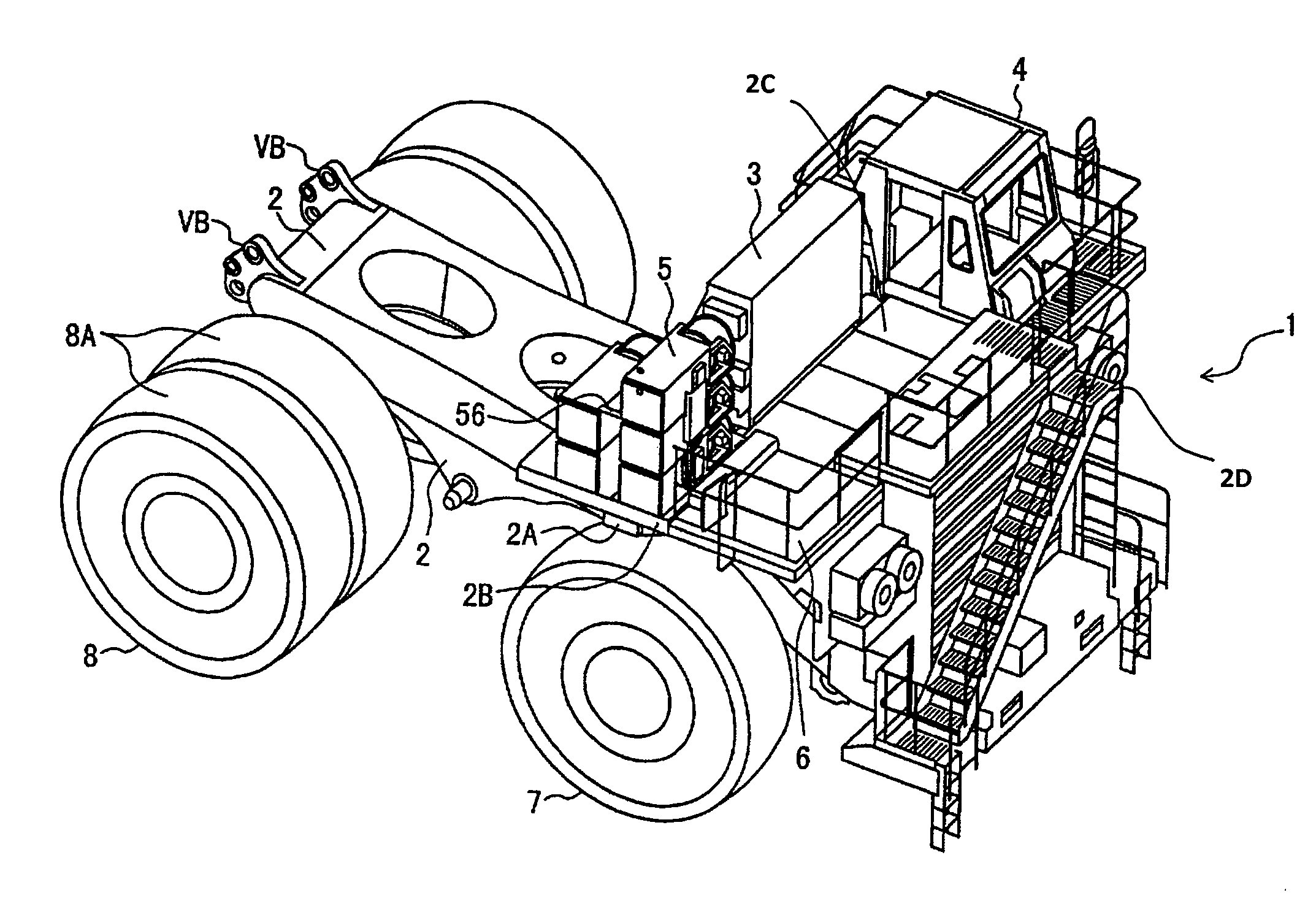
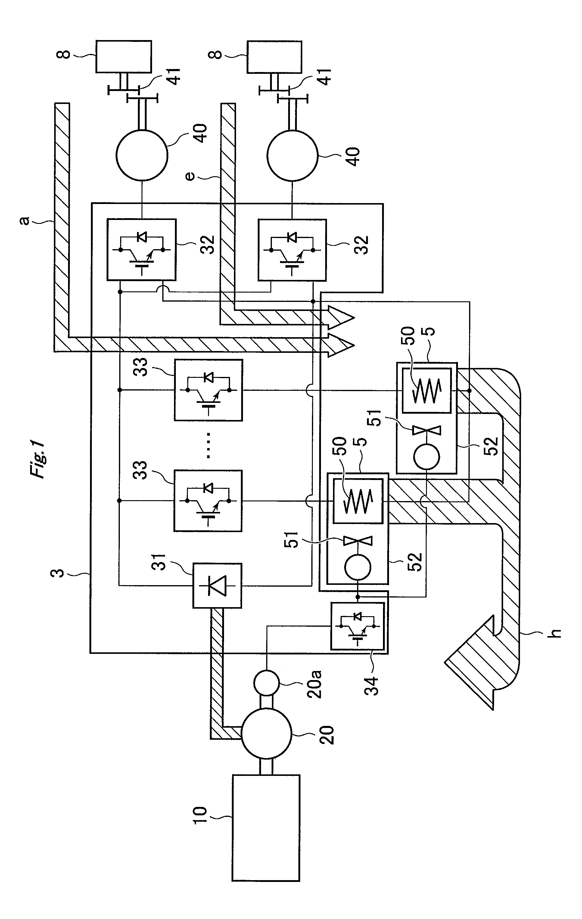
[0031]FIG. 1 is a conceptual diagram illustrating the structure of the drive unit of an electrically-driven dump truck 1 according to the invention. The drive unit comprises the following components: a diesel engine 10, or a prime mover (hereinafter referred to simply as “engine 10”); a main generator 20 connected to the engine 10 via a rotary shaft; an auxiliary generator 20a connected to the rotary shaft of the main generator 20; a control cabinet 3 that converts AC power from the main generator 20 into electric power at any desired frequency; wheel-drive electric motors 40 that obtain rotative power by receiving the electric power from the control cabinet 3; and resistor boxes 5 that each house a resistor 50 that consumes the regenerative electric power e that occurs during retarder braking operation.
[0032]The control cabinet 3 comprises the following components: a rectifier 31 that rectifies AC power from the main generator 20; inverters 32 that convert the rectified power by th...
second embodiment
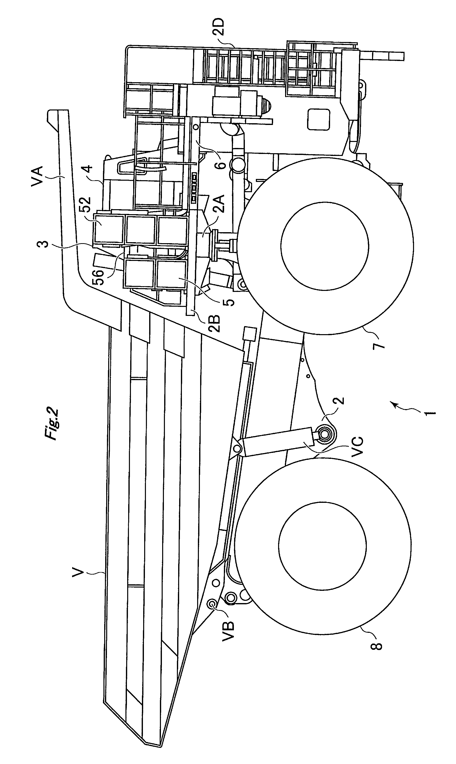
[0063]Since the outlet ports 54 of the resistor boxes 5 of the second embodiment are arranged so as to face forward, the warm air that results from cooling the resistors 50 is never blown toward the vessel V but discharged forward. Thus, the warm air will not stay below the canopy VA, and the control cabinet 3 and the cab 4, both of which are located to the left of the resistor boxes 5, remain unaffected by the warm air.
[0064]Further, since the cooling fans 51 of the resistor boxes 5 of the second embodiment face the slope section of the vessel V, the propagation of the noise of the cooling fans 51 into the cab 4 can be suppressed by the control cabinet 3. As a result, the noise level inside the cab 4 can be reduced, which in turn improves the operating environment inside the cab 4.
[0065]Although the arrangement of the resistor boxes 5 according to the second embodiment is such that the outlet ports 54 of the resistor boxes 5 face forward, the resistor boxes 5 can instead be arrange...
third embodiment
[0067]In the invention, a support frame 60 which is made, for example, of steel and substantially turned square U-shaped in cross-section is attached to the bottom section of the deck 6 with a flat section of the support frame 60 parallel to the deck 6. An extra resistor box 5 is mounted on this flat section of the support frame 60 with a longitudinal direction of the extra resistor box 5 parallel to a width direction of the body frame 2. The floor surface of the deck 6 under which the support frame 60 is attached is provided with a removable cover. In mounting the extra resistor box 5 on the support frame 60, the removable cover of the deck 6 is first removed, and the extra resistor box 5 is then mounted on the flat section of the support frame 60. Thereafter, the removable cover is attached back to the deck 6 so as to cover the upper section of the extra resistor box 5.
[0068]In the thus-configured electrically-driven dump truck 1 of the third embodiment as well, sufficient space c...
PUM
 Abstract
Description
Claims
Application Information
 - R&D
- Intellectual Property
- Life Sciences
- Materials
- Tech Scout
- Unparalleled Data Quality
- Higher Quality Content
- 60% Fewer Hallucinations
Browse by: Latest US Patents, China's latest patents, Technical Efficacy Thesaurus, Application Domain, Technology Topic, Popular Technical Reports.
© 2025 PatSnap. All rights reserved.Legal|Privacy policy|Modern Slavery Act Transparency Statement|Sitemap|About US| Contact US: help@patsnap.com


