

Temperature control element temperature control component, and waveguide opical module
Inactive Publication Date: 2005-06-30
IBIDEN CO LTD
View PDF4 Cites 8 Cited by
- Summary
- Abstract
- Description
- Claims
- Application Information
AI Technical Summary
Benefits of technology
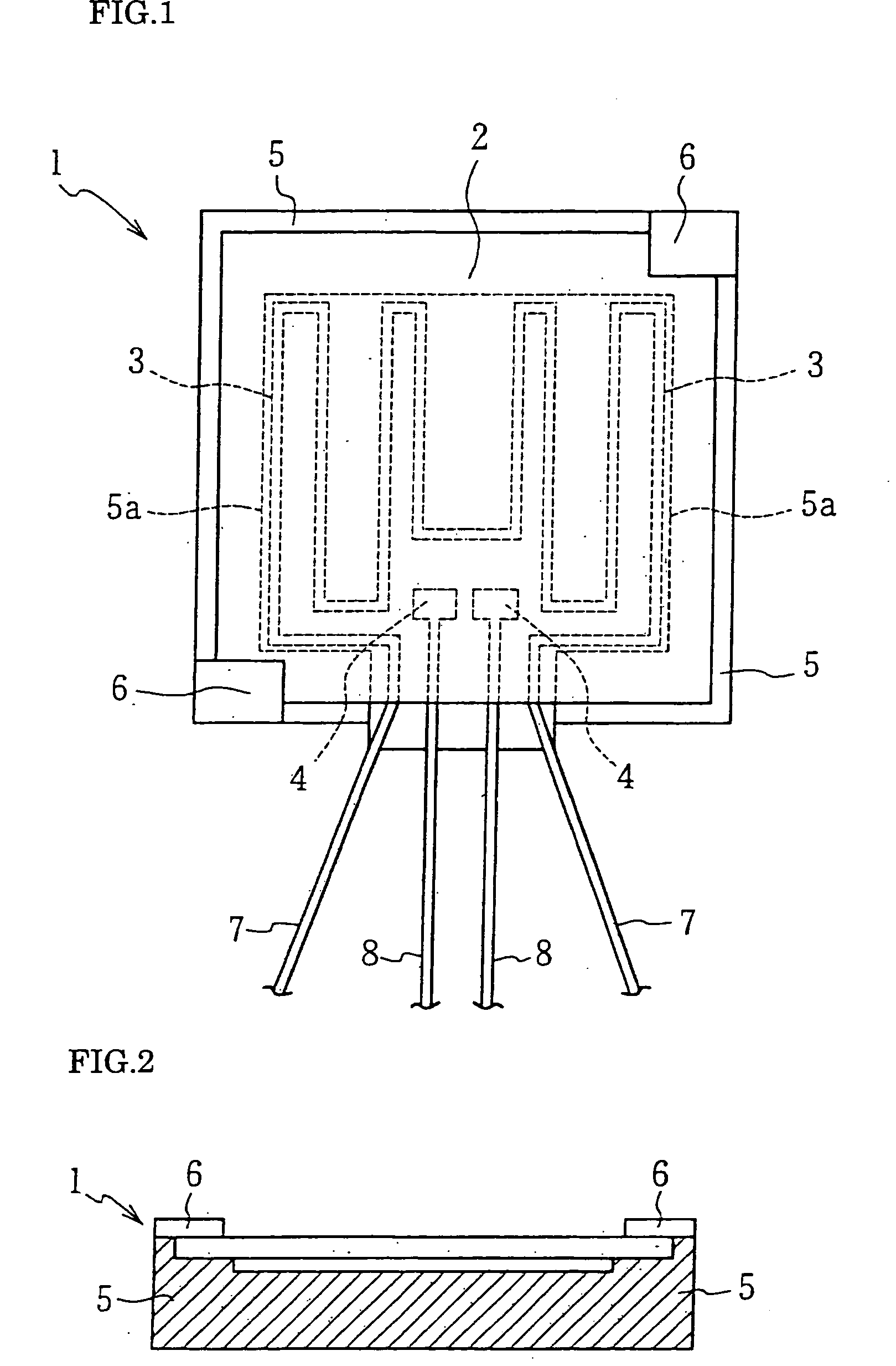
[0031] According to the present invention, the temperature control element has the heater or heat absorber provided on the non-heating side (rear side) surface of the plate or buried in the plate. Thus, the temperature control element has a function to elevate or lower the temperature of the plate appropriately. Also, since the plate can also function as a heat dispersion plate, it can effectively prevent the temperature distribution from being caused to be inhomogeneous because of the shape of the heater or heat absorber.
[0032] Further, since the total area of contact between the plate including the heater or heat absorber and the pedestal supporting the plate from below is more than 30% of the area of the non-heating side (rear side) of the plate to increase the supporting area, the plate itself will not be distorted or warped due to its own weight. Therefore, the flatness (warping) of the plate can be less than 50 μm, and thus even if the optical waveguide is mounted on the plate, the element will not have the optical axis thereof displaced by inclination or incur large propagation loss of light.
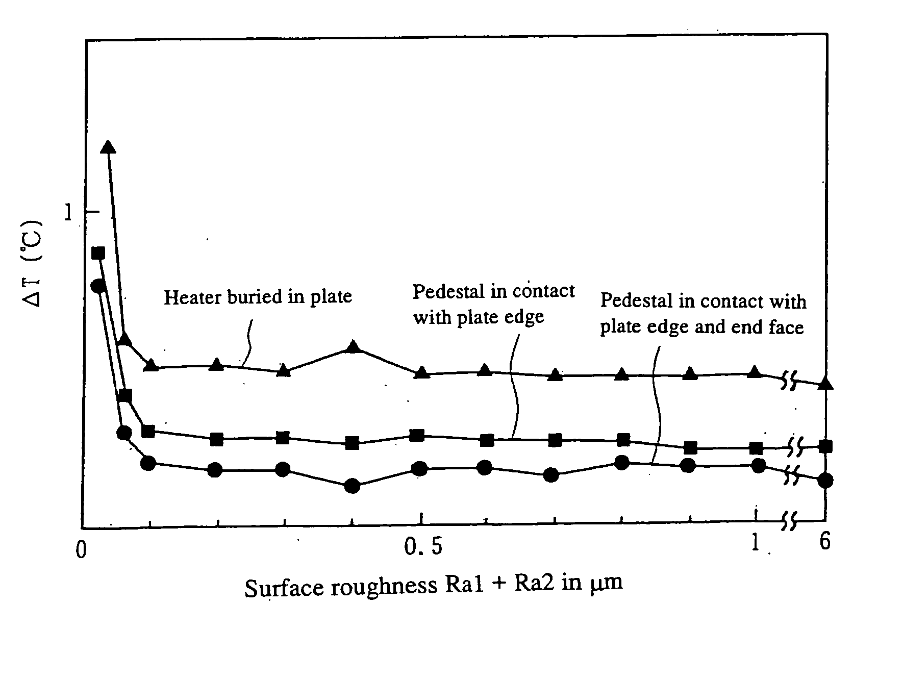
[0037] In this respect, in case an optical waveguide is supported in air in an optical part, the plate and pedestal are normally mirror-finished (Ra=0.01) by polishing to assure a flatness of them, and Ra1+Ra2 is about 0.02 μm. If the plate and pedestal are mirror-finished, however, the heat is easily propagated to the pedestal for dissipation, which will spoil the homogeneity of the temperature distribution over the plate surface. That is, the present invention is featured by the fact that the heat dissipation from the pedestal is prevented and also a cooling spot is prevented from taking place on the plate.
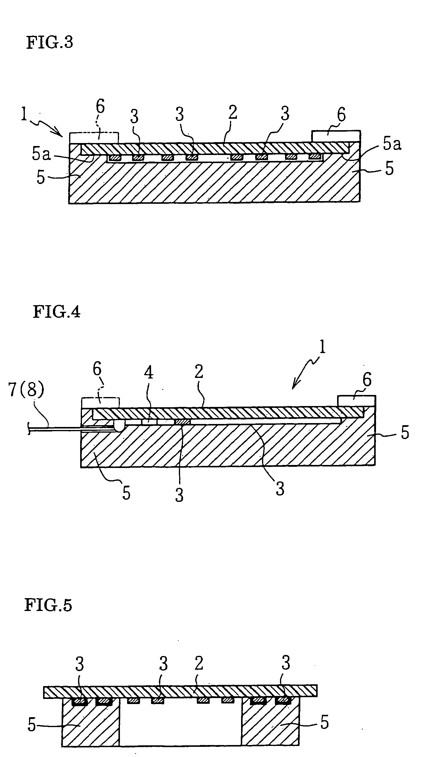
[0038] Another feature of the present invention lies in that the pedestal and plate are superposed one on the other with the thermal insulation laid between them at the contact between them. That is, as having previously been described, in case the sum of the area of contact between the pedestal and heater or heat absorber and that between the pedestal and plate is over 30%, the heat of the plate is easily conducted to the pedestal, which will lead to an inhomogeneous temperature distribution over the plate. On this account, according to the present invention, the thermal insulation is interposed between the plate and pedestal instead of the above-mentioned surface roughness control, in order to prevent the heat conduction from the plate toward the pedestal and assure a homogeneous temperature distribution over the plate.
[0040] Also, the plate abutting the pedestal is supported on the pedestal in contact with the edge thereof as well as in contact with the end face thereof. Thus, the end face of the plate will not be exposed to a fluidic atmosphere like air, and so the heat will not be dissipated to the atmosphere, and the heat conduction from the plate edge can be blocked.
[0041] Note that in case the pedestal is formed like a circular or square frame (cylinder or square column) and thus has a space defined inside thereof, air can be stayed in this space to store the heat, thereby effectively prevent any inhomogeneous temperature distribution from taking place.
Problems solved by technology
When the contact area is simply reduced, the plate will be warped or distorted, leading to impossibility of an homogeneous plate-surface temperature distribution, and rather a trouble will take place.
Method used
View moreImage
Smart ImageViewing Examples

Examples
example 4
[0122] The example 4 was tested under similar conditions to those in the testing on the example 1 except that the plate was applied with silicone resin, not roughened by sand-blasting, and fitted in the pedestal 5. The test was started after the silicone resin became dry. The silicone resin layer 13 was 100 μm thick, which yielded a flatness (warp) of 10 μm. With the thermo-viewer set to 80° C., the difference ΔT was observed to be 0.1° C.
Login to View More PUM
 Abstract
A temperature controller and temperature control element, whose plate-surface temperature distribution is highly homogeneous, which can be used in a waveguide type optical module. In a waveguide type optical module a temperature control element is supported on a pedestal inside a casing and an optical waveguide is mounted on the temperature control element. The temperature control element includes a plate having a heater or heat absorber provided on the non-heating side thereof or buried therein. The pedestal is provided to support the plate mainly in contact with the non-heating side of the plate. A total area of contact of the pedestal with the plate including an area of contact with the heater or heat absorber is set to over 30% of the area of the non-heating side of the plate and a sum of surface roughness of the pedestal and those of both the plate and heater is set to over 0.05 μm.
Description
FIELD OF THE INVENTION [0001] The present invention relates to a temperature control element and temperature controller used for controlling the temperature of an optical waveguide having a temperature-dependent characteristic and a waveguide type optical module in which the temperature controller or temperature control element is installed. BACKGROUND ART [0002] The conventional waveguide type optical module, especially, the quartz-array waveguide type optical module with a wavelength multi / demultiplexing function, uses a waveguide having a temperature-dependent wavelength demultiplexing characteristic. The waveguide type optical module of this type needs a temperature control of the waveguide for maintaining a required wavelength demultiplexing characteristic. Also an optical modulator or an optical switch, whose refractive index is adjusted by changing the temperature for the optical deflection, should have the temperature thereof adjusted for the refractive index not to vary. Bo...
Claims
Login to View More Application Information
Patent Timeline
 IPC IPC(8): G02B6/12G02B6/42
CPCG02B6/12007G02B2006/12135G02B6/4201G02B6/4271
InventorMORI, MIKIOSAKAMOTO, HAJIMEITO, YASUTAKA
OwnerIBIDEN CO LTD