Bent pre-tensioner tube

a pre-tensioner tube and tube body technology, applied in the direction of safety belts, explosive-based starters, pedestrian/occupant safety arrangements, etc., can solve the problems of corresponding costs and effort in designing the known pre-tensioning device, and achieve the effect of improving the fixing of the bent tub

Active Publication Date: 2011-09-06
AUTOLIV DEV AB
View PDF24 Cites 6 Cited by
  • Summary
  • Abstract
  • Description
  • Claims
  • Application Information

AI Technical Summary

Benefits of technology

[0007]The invention involves the advantage that because of the separation of the section which accommodates the gas generator and the piston path section, a sufficiently large pressure can built up in the section for accommodating the gas generator in order to ensure clean and complete combustion of the material which creates the gas, even at low temperatures. Because of the restricted cross-sectional are of the gas flow path provided between the aforementioned sections of the tube, no pressure peak occurs in the piston path section, so that thinner drive cables can be used. The pressure losses which occur in the area of the cable seal are correspondingly less. A further advantage consists in the fact that the gas pressure which is developed in the piston path section which affects the piston is maintained over a longer period in an even fashion, as a gas stream is correspondingly fed in from the gas generator section in a regulated and continuous way. Based on the design of the narrowing of the cross-section of the bent section in relation to the tube which is used, adaptations in the design of the pre-tensioning device can easily be made to fit for application conditions within a seat belt system.
[0008]According to one embodiment of the invention it is intended that the narrowing of the cross-section of the tube in the bent section is effected by deforming the tube. This leads to the advantage of simple manufacturing of the pre-tensioning device without additional devices having to be inserted into the tube. According to alternative embodiments of the invention, the narrowing of the cross-section of the bent section can be achieved by means of rolling or bending of the tube.
[0009]In so far as, in a particular embodiment of the invention with a bending of the tube it is provided for that the tube is bent to form the bent section using suitable bending tubes which limit the width of the tube during the bending process in such a way that a hollow throat is impressed into the outer wall of the tube at the bent section which exhibits the larger bending radius, and the cable section is deflected via the bent section of the tube, the particular advantage results that because of the tube bend which is created in a particular way and the form of the bent section of the tube, the bent section itself forms the cable deflection guide, so that a separate cable guide as a component, and also mounting of such a separate component are not needed, in contrast to the state of the art. The pre-tensioning device can be manufactured with fewer components and therefore altogether more cost-effectively, and finally, the pre-tensioning device according to the invention is compact and can therefore be accommodated in a motor vehicle in space-saving fashion.
[0010]With regard to the form of the bent section, according to one embodiment of the invention it is provided that the inner wall of the tube is brought into contact at the inner side of the hollow throat impressed into the bent outer wall at its narrowest bent point with its inner side, and, in the ears formed on both sides of the narrow throat between the outer wall and inner wall, gas guide channels are formed for guidance of the gas from the section of the tube which accommodates the gas generator into the section of the tube which forms the piston path. Based on the bent section created in this way, defined cross-sections for the gas guide channels result, which is an advantage for the safe function of the pre-tensioning device.
[0015]According to one embodiment of the invention it can be provided that the fixing part springs into the inner angle of the bent tube with an interference fit with a projection adapted to the shape of the inner wall of the bent tube which encloses the internal angle and supports the inner wall of the bent tube. This improves fixing of the bent tube and its design in general.

Problems solved by technology

The known pre-tensioning device is associated with the disadvantage that the pressure of the gas generated by the gas generator is led directly to the piston through the section of the tube which has a constant cross-sectional shape.
This means that the pressure peak which is created after ignition of the gas generator and before the movement of the piston necessitates sufficient strength of the drive cable and the connection of the cable with the piston as well as a correspondingly good seal of the cable entry into the tube, which gives rise to corresponding costs and effort when designing the known pre-tensioning device.

Method used


Image

  • Bent pre-tensioner tube
  • Bent pre-tensioner tube
  • Bent pre-tensioner tube

Examples


Embodiment Construction

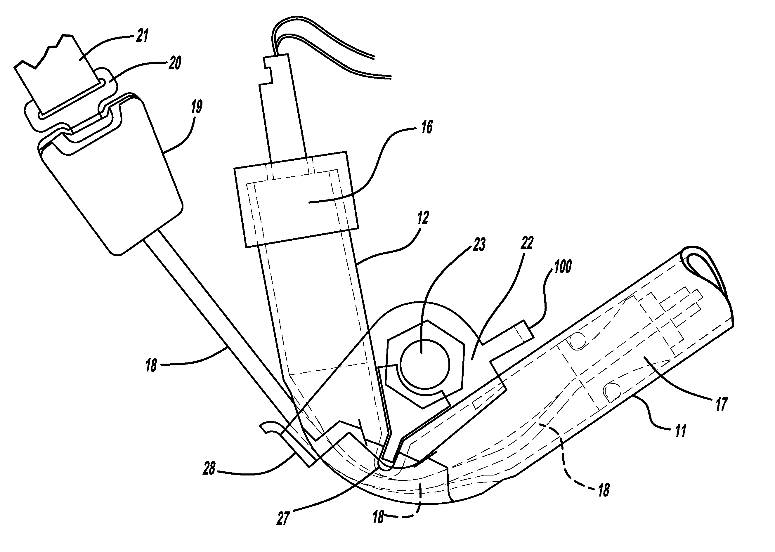
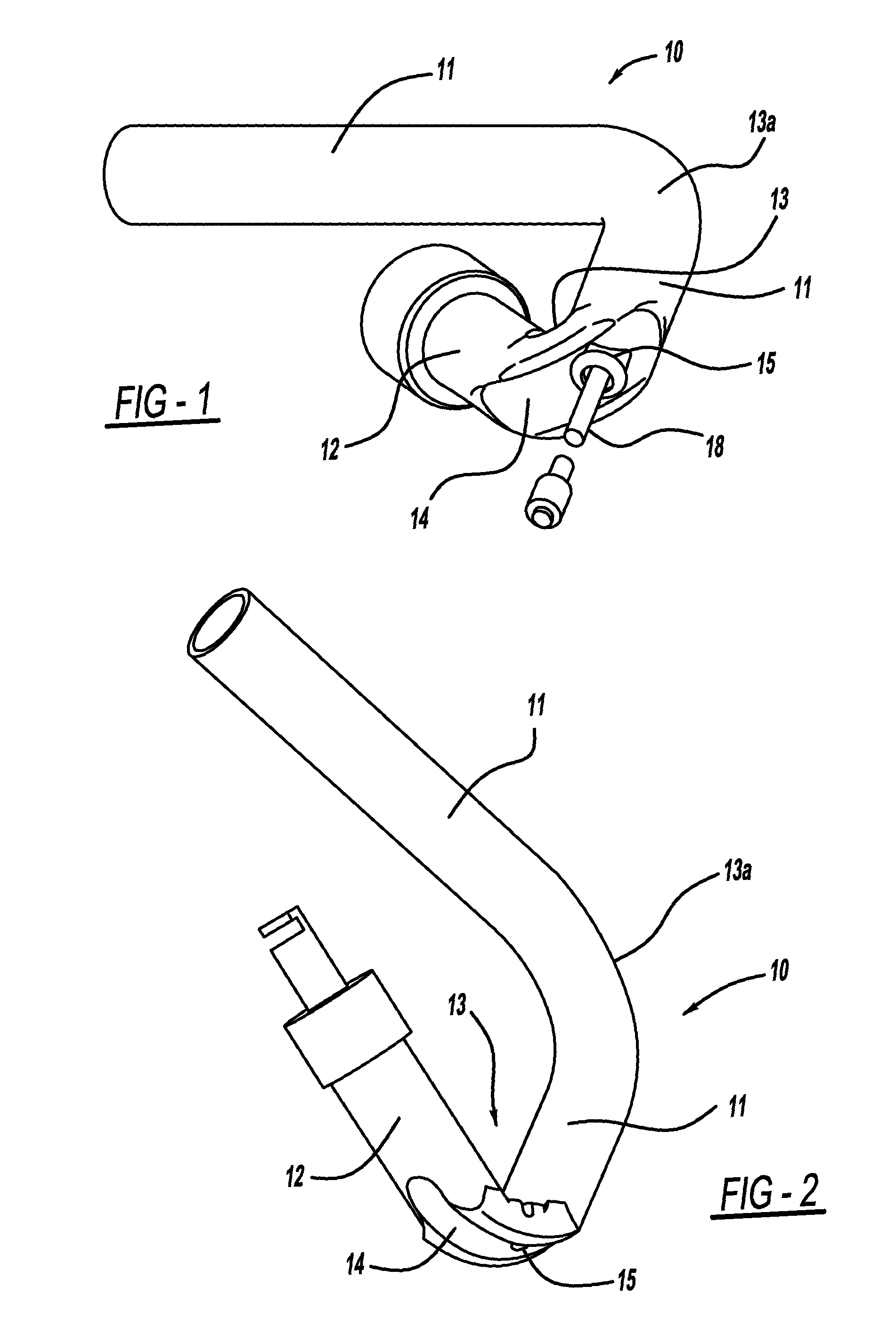
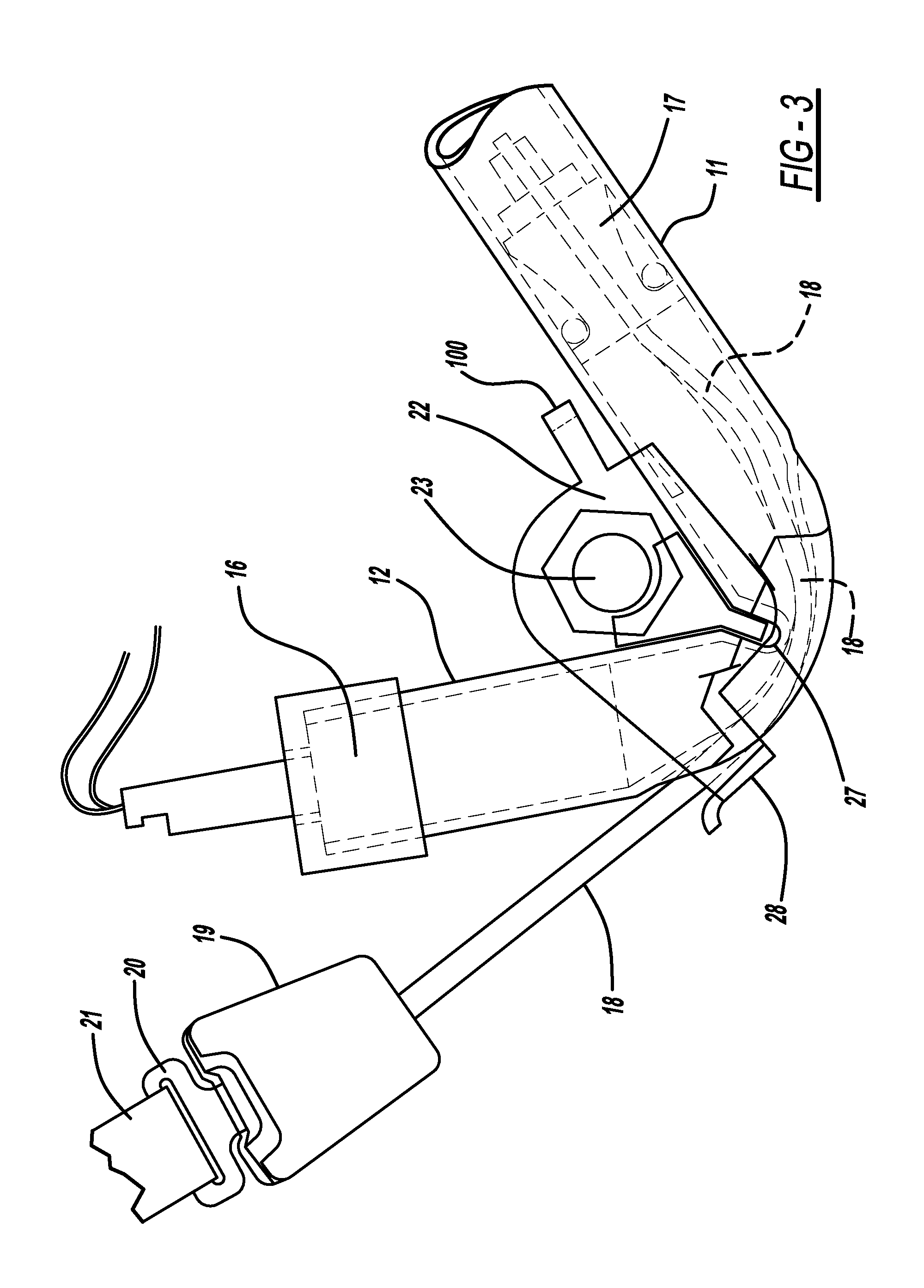
[0026]First of all referring to FIGS. 1 and 2, a bent tube 10 can be recognised as a component of the drive for the pre-tensioning device shown as a whole in FIG. 3, whereby tube 10 shown in the embodiment forms a piston path section 11 forming a piston path and a gas generator section 12 which accommodates a gas generator. At bent section 13 which separates gas generator section 12 and piston path section 11 from one another, a narrowed cross-section is formed, with a defined flow path for gas generated by the gas generator 16 which is to be introduced into piston path section 11 is formed as gas guide channels 29 (FIG. 6). At bent section 13, a hollow throat 14 is impressed into the tube outer wall at the outside surface of the bend with the use of corresponding bending tools for creating the tube bend, and a cable opening 15 for insertion of a cable section is formed on the area of bent section 13 which faces gas generator section 12. In the embodiment shown, the tube section con...


PUM


Abstract

A pre-tensioning device for a seat belt with a piston which is guided in a bent tube, and which in case of triggering is influenced by gas generated by a gas generator located in one section of the tube, to which a cable led into the tube by a cable opening is attached. The gas generator section (12) of tube (10) which accommodates gas generator (16) is offset from the piston path section (11) of tube (10) which accommodates piston (17) by creation of a narrowed cross-section inside the tube with a defined gas flow path (29, 41).

Description

CROSS REFERENCE TO RELATED APPLICATIONS[0001]This application claims priority to DE 10 2004 032 063.2, filed Jul. 1, 2004 and PCT / EP2005 / 006506, filed Jun. 17, 2005.FIELD OF THE INVENTION[0002]The invention relates to a pre-tensioning device for a seat belt with a piston, which is guided in a tube and which in case of triggering is forced to move by gas generated by a gas generator located in one section of the tube, to which a section of cable led into the tube through a cable opening is attached.BACKGROUND OF THE INVENTION[0003]A tensioning device with the aforementioned characteristics is described in EP 1 283 138 A1; the known pre-tensioning device consists of a tube which is bent for better packaging and assembly in the often limited space available in a motor vehicle for the accommodation of a drive which is necessary for the pre-tensioning process, which forms a straight section which accommodates a piston and therefore forms a piston path section, and a tube section which is...

Claims


Application Information

Patent Timeline
Patent Type & Authority Patents(United States)
IPC IPC(8): B60R22/195
CPCB60R22/1952B60R22/1955B60R22/4633B60R2022/1806B60R2022/4695B60R22/195B60R22/46
Inventor SINGER, KLAUS-PETER
Owner AUTOLIV DEV AB
Why Eureka
Try Eureka