Folding rear sight with dual purpose sighting elements

a rear sight and dual-purpose technology, applied in the field of weapons sighting devices, can solve the problems of affecting the field use of firearms, so as to achieve quick and easy deployment

Active Publication Date: 2011-09-13
SWAN RICHARD E
View PDF53 Cites 63 Cited by
  • Summary
  • Abstract
  • Description
  • Claims
  • Application Information

AI Technical Summary

Benefits of technology

[0011]Accordingly, when the large aperture sight is desired, the small aperture sight can be folded down out of the way of the large aperture. Further, when the sight housing is placed into the stored position, i.e. folded down against the base, the two elements of the aiming system can fold against one another allowing the sight housing to store tightly against the base while preventing one of the sighting elements from protruding outwardly from the firearm.
[0013]Accordingly, it is an object of the present invention to provide a sighting mechanism for a firearm that includes at least two aiming elements and has a compact profile when placed into a storage position. It is a further object of the present invention to provide a sighting mechanism for a firearm that can be retracted to a low profile storage position against the contour of the firearm while being quickly and easily deployable to a fully aligned active position. It is yet a further object of the present invention to provide a retractable sighting assembly for a firearm that includes at least two user selectable aiming elements that can be fully retracted into a low profile storage position against the contour of the firearm.

Problems solved by technology

Generally, sighting mechanisms for firearms are bulky and protrude outside the firearm's general contour.
This construction creates a greater opportunity for the sighting mechanism to be caught on clothing or brush while the firearm is being carried thereby knocking the sighting mechanism out of alignment.
Although this re-alignment step may be acceptable when the firearm is used in a controlled environment such as a firing range, it is not acceptable for a firearm employed for field use, such as hunting or combat environments where immediate, fully aligned use of the sight is required.
However, this device has a relatively large vertical profile, even when it is in stowed position.
Accordingly, the sighting mechanism has a profile that is larger than desired and which tends to interfere with the mounting of additional accessories above the sight.
In addition, as the military becomes more involved in close quarter battle (QCB) situations, it has been identified that another perceived shortcoming of the prior art is that conventional back-up iron sights including aperture type sighting elements are sometimes difficult to use in close quarter battle, and / or not versatile enough to provide both CQB sighting and long range sighting.
The use of a larger aperture is effective in non-combat, practice-range situations to provide a bigger sight window in order to line up the front post, but has not been found to be ideal in actual combat where it is critical to get the weapon on target with minimal effort.

Method used


Image

  • Folding rear sight with dual purpose sighting elements
  • Folding rear sight with dual purpose sighting elements
  • Folding rear sight with dual purpose sighting elements

Examples


Embodiment Construction

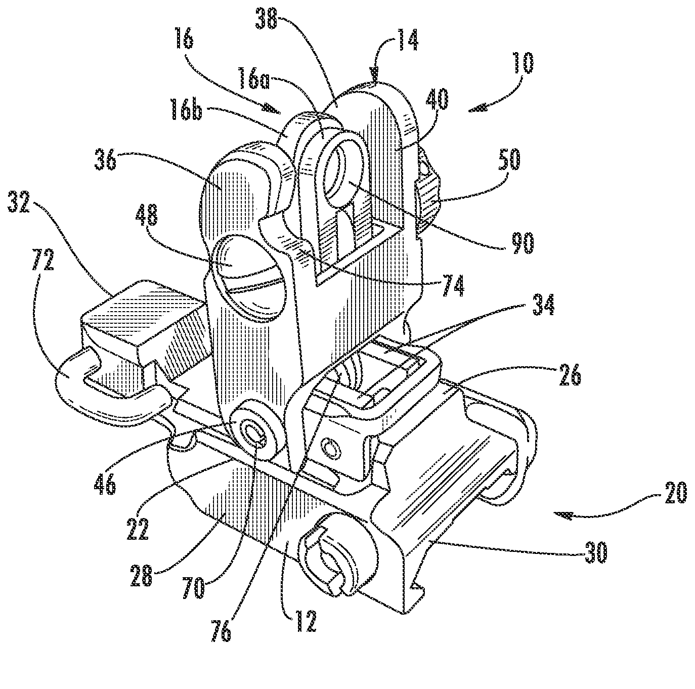
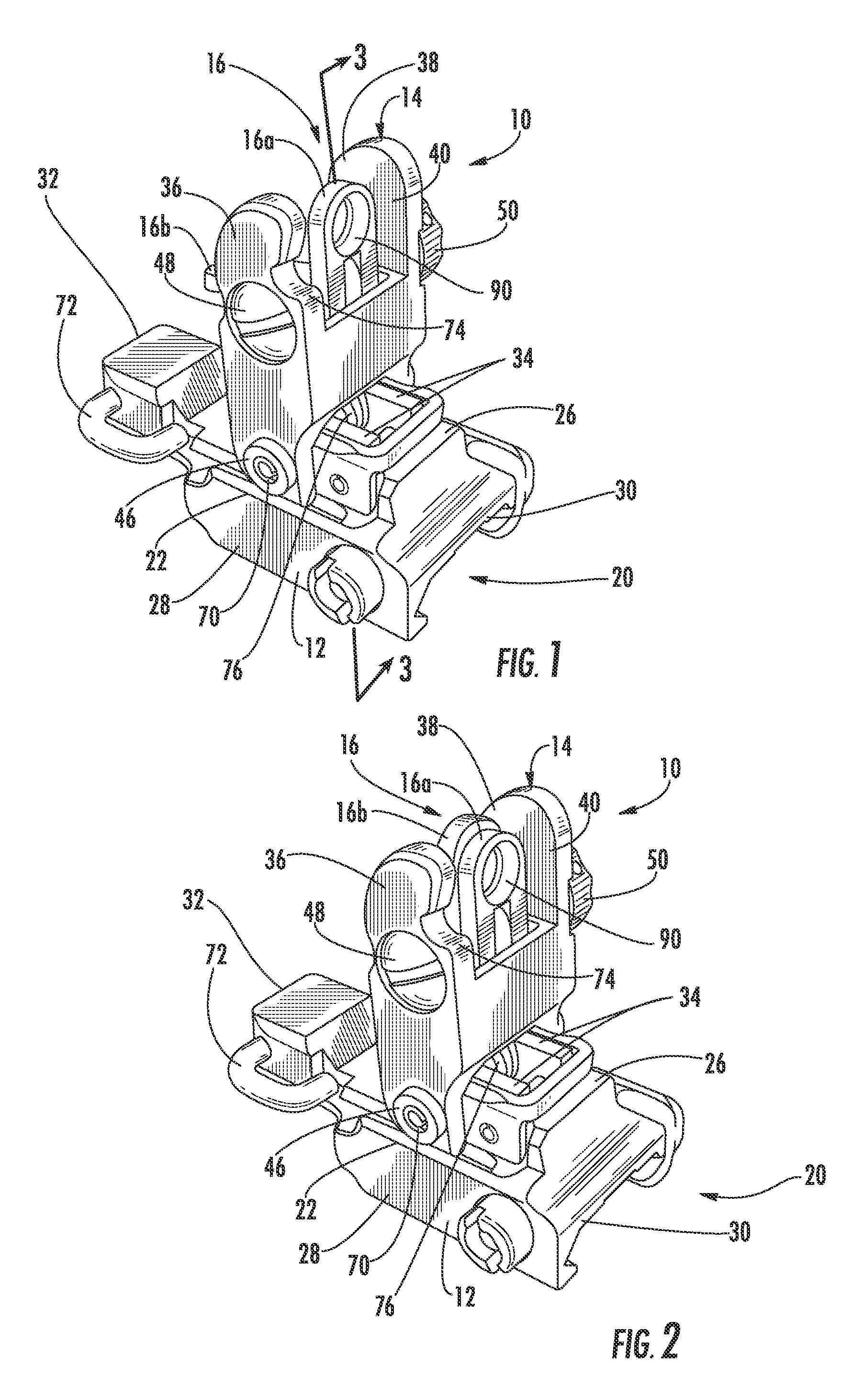
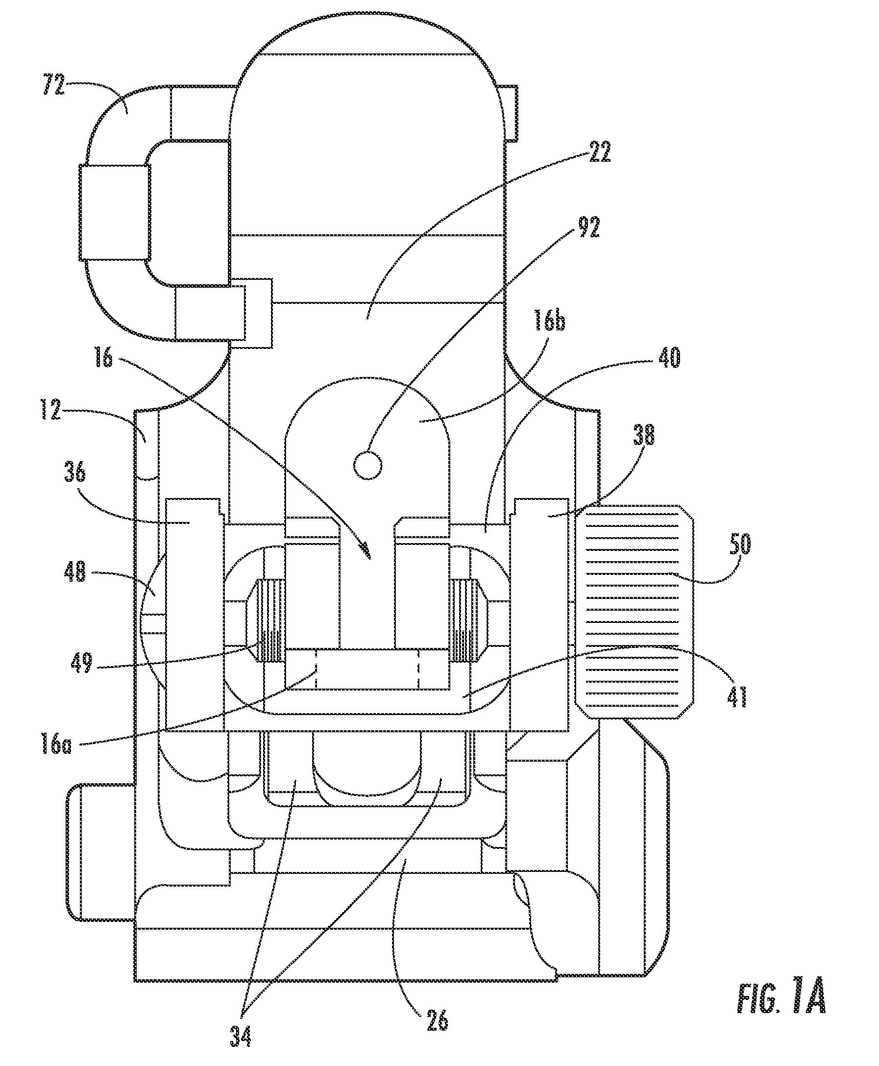
[0027]Now referring to the drawings, the folding rear sight of the present invention is shown and generally illustrated at 10 in the drawing figures. In particular, the present invention provides folding rear sight 10 having a reduced vertical profile when in the stowed position. This feature allows improved shielding and protection of the aiming elements within the sighting device 10 when in the stowed position.

[0028]Referring briefly to FIG. 5, the folding rear sight 10 is used as the rear sight on an M4 / M16 type rifle generally indicated at 80 (M4 and M16 are trademarks of Colt Manufacturing Inc.). The weapon 80 employs both a front sight 81 and the present rear sight 10 for aiming. The weapon 80 generally includes an upper receiver 82 with a longitudinal dovetail rail 83, as well as a lower receiver 84, a butt stock 85 and a barrel 86. The front sight 81 is mounted on the front end of the barrel 86 and comprises an upright post 87. The tip of the post 87 is placed on the target ...


PUM


Abstract

A folding rear sight includes a base member and a spring-loaded sight housing that deploys into an operational position with a simple release lever. The sight includes two separate dual-purpose aiming elements, one fixed, and one that rotates between an inactive position and an active position in front of the fixed element. The top aiming end of the fixed aiming element includes a large diameter close quarter battle (CQB) aperture and an vertically extending sighting notch configured and arranged above the large CQB aperture. The top aiming end of the rotatable aiming element includes a smaller, long-range sighting aperture and an elongated vertically extending sighting notch configured and arranged above the smaller sighting aperture. The dual-purpose aiming elements provide standard aperture sights for situations where the soldier has reasonable time to aim the weapon. The notched sights above the apertures provide a larger, open sighting window, which is easier to align in stressful close combat situations, as well as long range sighting.

Description

CROSS-REFERENCE TO RELATED APPLICATIONS[0001]This application is related to and claims priority from earlier filed U.S. Provisional Patent Application No. 60 / 511,878, filed Oct. 16, 2003, the contents of which are fully incorporated herein by reference.[0002]The Application is also a continuation-in-part of currently pending U.S. patent application Ser. No. 10 / 939,962 filed Sep. 14, 2004.BACKGROUND OF THE INVENTION[0003]The present invention relates generally to sighting devices for weapons. More specifically, the present invention relates to a low profile configuration for a folding rear sight.[0004]Generally, sighting mechanisms for firearms are bulky and protrude outside the firearm's general contour. This construction creates a greater opportunity for the sighting mechanism to be caught on clothing or brush while the firearm is being carried thereby knocking the sighting mechanism out of alignment. Prior art devices that have attempted to address this problem by allowing removal...

Claims


Application Information

Patent Timeline
Patent Type & Authority Patents(United States)
IPC IPC(8): F41A15/00
CPCF41G1/065F41G1/08F41G1/17F41G1/42
Inventor SWAN, RICHARD E.
Owner SWAN RICHARD E
Why Eureka
Try Eureka