
Wheel reconditioning station and method of use

a wheel reconditioning station and wheel mounting technology, which is applied in the direction of wheel mounting apparatus, vehicle cleaning, ways, etc., can solve the problems of potential value of the vehicle, affecting the overall appearance of the vehicle, etc., and achieves the effect of quick and easy deployment to engag

Active Publication Date: 2005-02-24
ULTIMATE TECH
View PDF17 Cites 1 Cited by
  • Summary
  • Abstract
  • Description
  • Claims
  • Application Information

AI Technical Summary

Benefits of technology

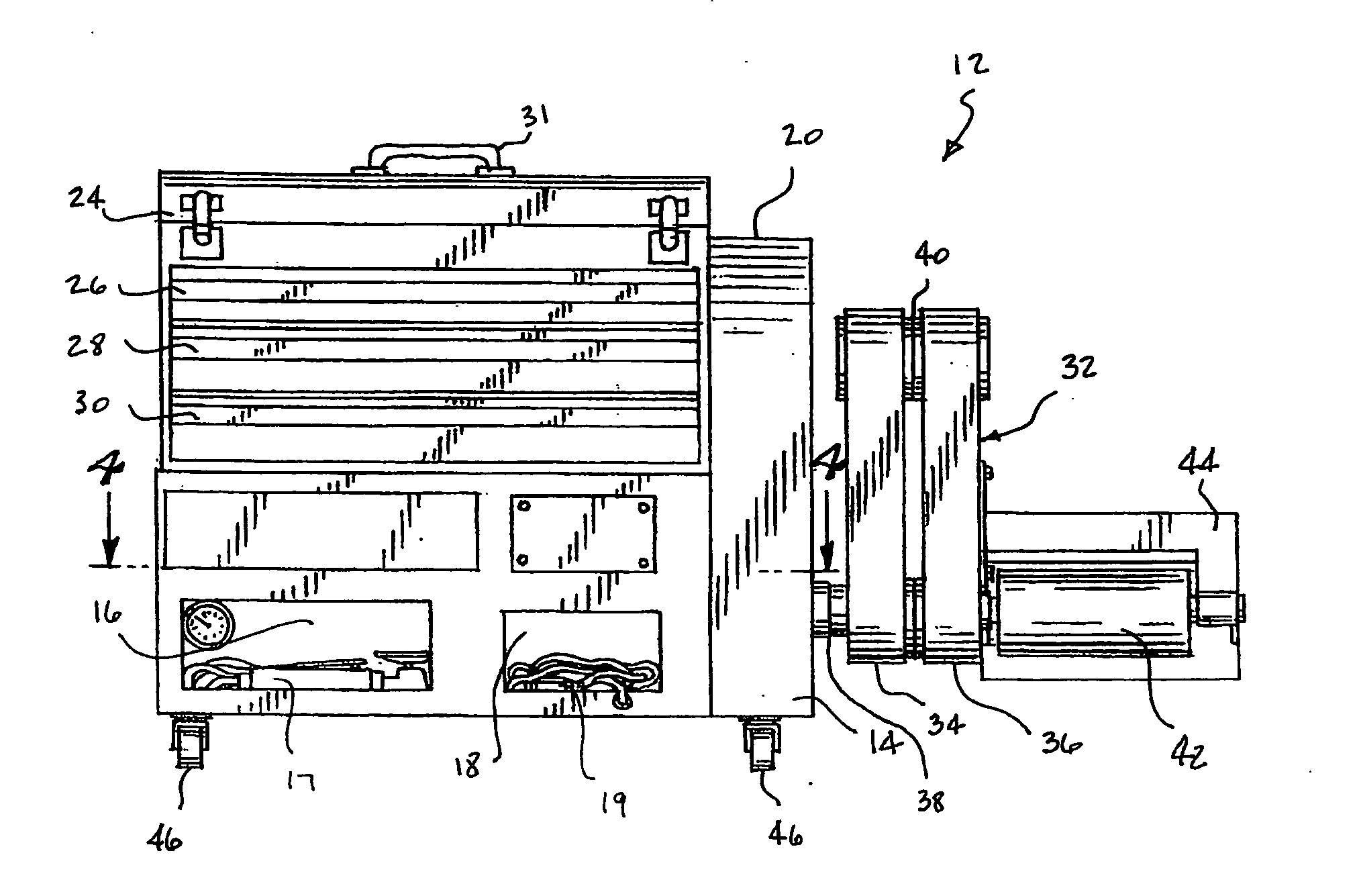
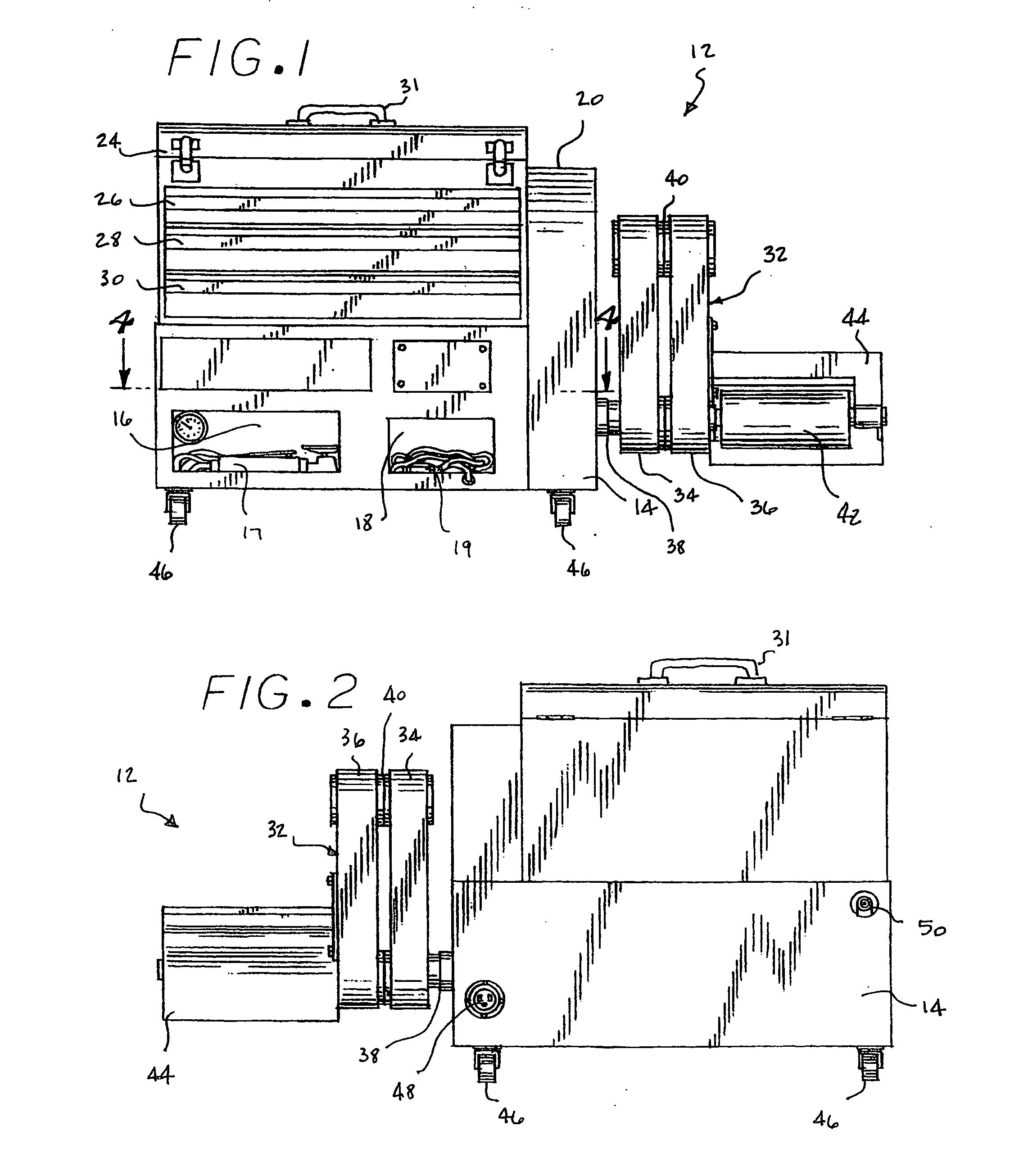
[0007] The reconditioning station of the present invention comprises a compact and portable device that is quickly and easily deployable to engage a tire surface and rotate the wheel and tire combination while additionally providing ready access to all of the various tools and materials that are needed by a technician to effect a wheel repair. The station includes an articulating arm that renders the station compact while in its stowed configuration yet capable of engaging a wide variety of vehicle wheels including wheels mounted to low slung automobiles with limited access. The method of the present invention comprises the efficient use of such station to effect a wheel repair.
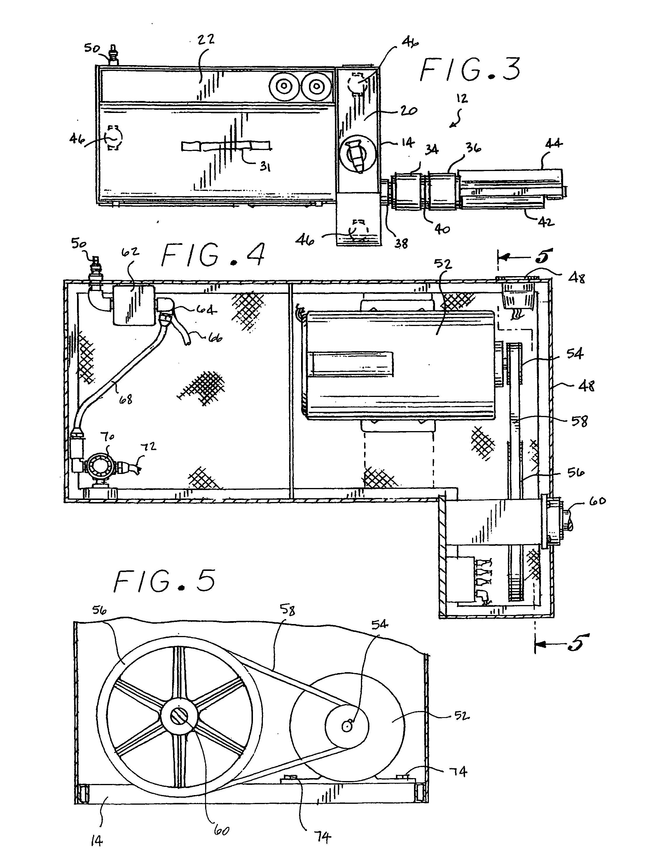
[0009] The articulating arm has a proximal member and a distal member. The drive roller extends laterally from the distal end of the distal member and includes an anchoring cradle which engages the ground upon deployment of the arm so as to support the drive roller under the weight of the wheel and tire combination placed thereon as well as prevent the roller and hence the arm and reconditioning station from shifting as torque is applied to the wheel by the drive roller. The cradle additionally serves the function of locking the arm in its folded position during transport of the reconditioning station. The reach and lateral offset of the arm allows a powerful drive motor to be used without compromising the ability of the device to engage a wheel and tire combination mounted to a vehicle with limited accessibility.
[0011] The method of the present invention requires the transportation of the workstation to the jobsite, hookup to a remote source of electrical power and compressed air and the unfolding of the articulating arm. The corner of the vehicle with the wheel in need of repair is jacked up slightly, the drive roller is positioned thereunder and the vehicle is lowered so that the tire exerts a slight pressure on the drive roller. The various pneumatic tools, already connected to their respective sources of compressed air are extracted from their storage compartments and the permanently wired footpedal is retrieved from its storage compartment. As such, the configuration of the workstation requires only a minimal number of interconnections to be made which enables a technician to be ready to commence a repair within a very few minutes after arriving at a jobsite.
[0012] By actuating the footpedal, the technician can quickly and easily index a wheel into a desired position to most effectively access a damaged area with a particular power tool or can rotate the wheel while such powertool is being applied to a particular wheel surface to enable the creation of a smooth transition from the repaired area to the rest of the wheel. The ability to rotate and / or index the wheel via handsfree control greatly simplifies and expedites the various grinding, polishing, cleaning, masking and finishing operations. The variable speed control allows the speed of rotation to be tailored to the requirements of a particular reconditioning step. Because the consumables, e.g. the cleaners, adhesion promoters, paints and even rags are maintained by the workstation within easy reach of the technician, the reconditioning process can proceed at a rapid pace. After the repair is complete, the air tools and footpedal are restowed in their respective compartments and the station is disconnected from the air and power sources. A quick jacking of the wheel allows the drive roller and arm to be extracted from thereunder and the arm to be folded into its compact configuration against the station after which the entire station can be lifted into the technician's truck for transport to the next jobsite.

Problems solved by technology

Automotive road wheels are easily damaged such as for example by contact with a curb during parking maneuvers, incompatibility with automatic carwash equipment or by the careless mounting or dismounting of a tire.
While the damage that results is usually not structural it is nonetheless unsightly and detracts from the overall appearance and potentially the value of the vehicle.

Method used


Image

  • Wheel reconditioning station and method of use
  • Wheel reconditioning station and method of use
  • Wheel reconditioning station and method of use

Examples


Embodiment Construction

[0029] The Figures generally depict a preferred embodiment of the present invention. The device comprises a self-contained wheel reconditioning station that not only enables a technician to rotate or index the wheel to be reconditioned while leaving the technician's hands free to manipulate any of various handtools that are used during the reconditioning process but additionally arrays all of the tools and materials that are needed in a readily accessible fashion.

[0030]FIG. 1 is a front plan view of the of the reconditioning station 12 of the present invention. The reconditioning station 12 includes a chassis 14 which defines and / or supports a plurality of storage compartments 16, 18, 20, 22, 24, 26, 28 and 30 and includes an articulating arm 32 that is mounted to one side thereof. Storage compartments 24, 26, 28, 30 can be lifted off of the chassis as a unit wherein grasp handle 31 is jilted for such purpose. When in place, the storage compartments appear integral with the chassis...


PUM

PropertyMeasurementUnit
speedaaaaaaaaaa
rotational speedaaaaaaaaaa
rotationaaaaaaaaaa

Abstract

The present invention provides a compact and portable reconditioning station that avails all of the tools and materials that a technician needs for reconditioning a wheel. Additionally, the station enables the technician to rotate and index the wheel by depression of a footpedal to leave his hands free to manipulate the various tools that are used during the reconditioning process. The reconditioning station is easily transportable in its compact stowed configuration and is quickly deployable at the jobsite.

Description

CROSS REFERENCE TO RELATED APPLICATION [0001] This is a non-provisional application claiming priority to provisional application No. 60 / 496,275, entitled Wheel Indexing and Rotating Apparatus, filed on Aug. 19, 2003, which is hereby incorporated by reference in its entirety.BACKGROUND OF THE INVENTION [0002] The present invention generally relates to the reconditioning or custom painting of an automotive road wheel while the wheel remains attached to an automobile and while the wheel has a tire mounted thereon. More particularly, the invention pertains to a compact and portable workstation that enhances a technician's ability to recondition such wheel as well as to methods for reconditioning the wheel using such workstation. [0003] Automotive road wheels are easily damaged such as for example by contact with a curb during parking maneuvers, incompatibility with automatic carwash equipment or by the careless mounting or dismounting of a tire. While the damage that results is usually ...

Claims


Application Information

Patent Timeline
Patent Type & Authority Applications(United States)
IPC IPC(8): B23P6/00B24B5/44B60BB60K17/35B62D61/12B66F5/00
CPCB24B5/44Y10T29/49542Y10T29/53448B23P6/00
Inventor IRBY, PATRICK A.IRBY, JASON R.
Owner ULTIMATE TECH
Learn More