Damping mechanism

a damping mechanism and leaf valve technology, applied in the direction of shock absorbers, dampers-spring combinations, vibration dampers, etc., can solve the problems of inherently large size of the damping mechanism using a leaf valve, energy loss in the working fluid, and generation of damping force, etc., to achieve convenient operation and convenient operation. , the effect of simple construction

Inactive Publication Date: 2011-09-13
KYB CORP
View PDF8 Cites 10 Cited by
  • Summary
  • Abstract
  • Description
  • Claims
  • Application Information

AI Technical Summary

Benefits of technology

[0008]It is therefore an object of this invention to provide a damping mechanism which can generate a damping force having preferable characteristics while maintaining a simple construction.

Problems solved by technology

In this damping mechanism, when the piston strokes at a high speed, the damping force is generated by the flow resistance of the leaf valve and an energy loss in the working fluid due to friction when it passes through the port.
As a result, a damping mechanism using a leaf valve is inherently large in size and a manufacturing cost thereof tends to be high.

Method used


Image

  • Damping mechanism
  • Damping mechanism
  • Damping mechanism

Examples


Embodiment Construction

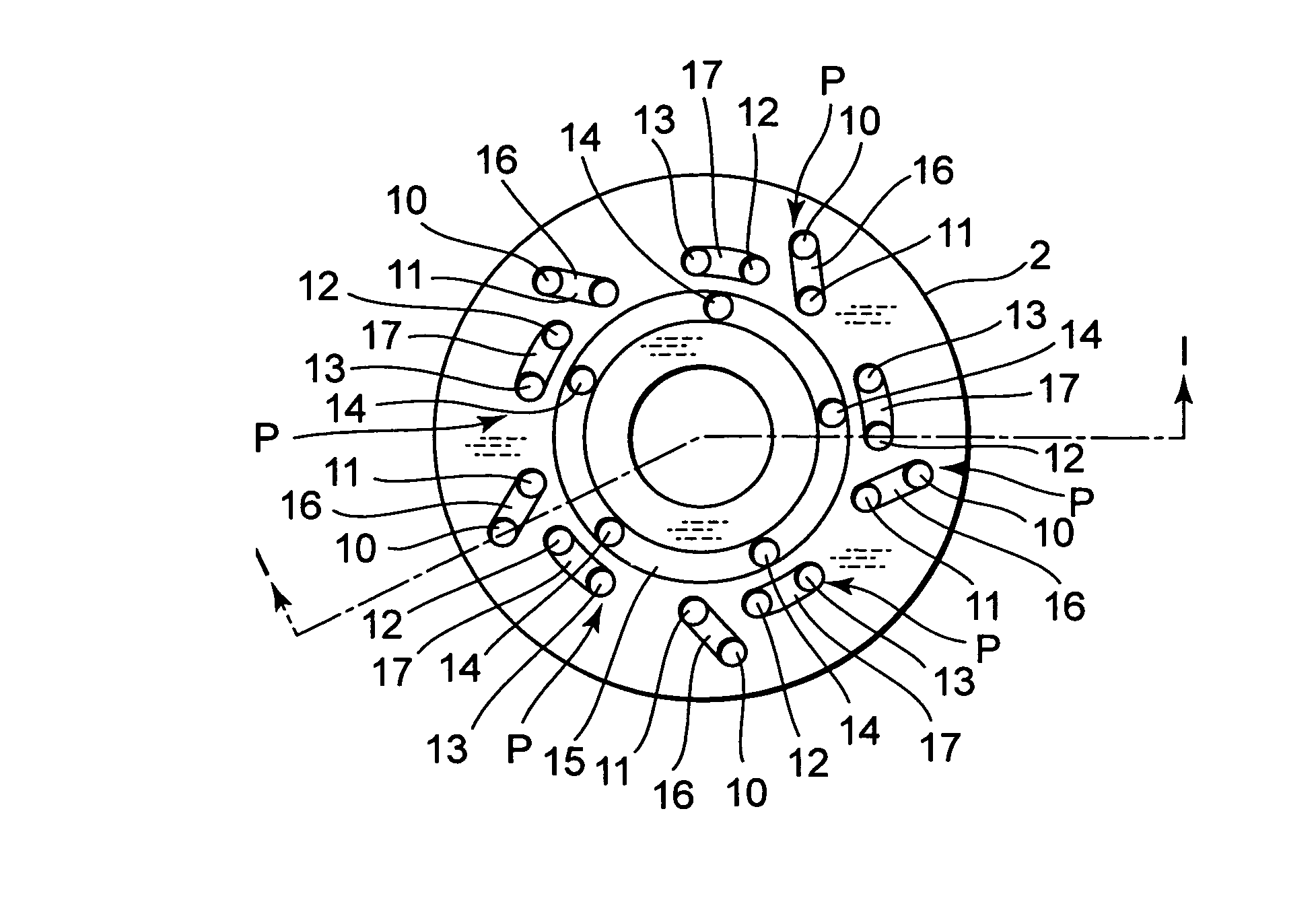
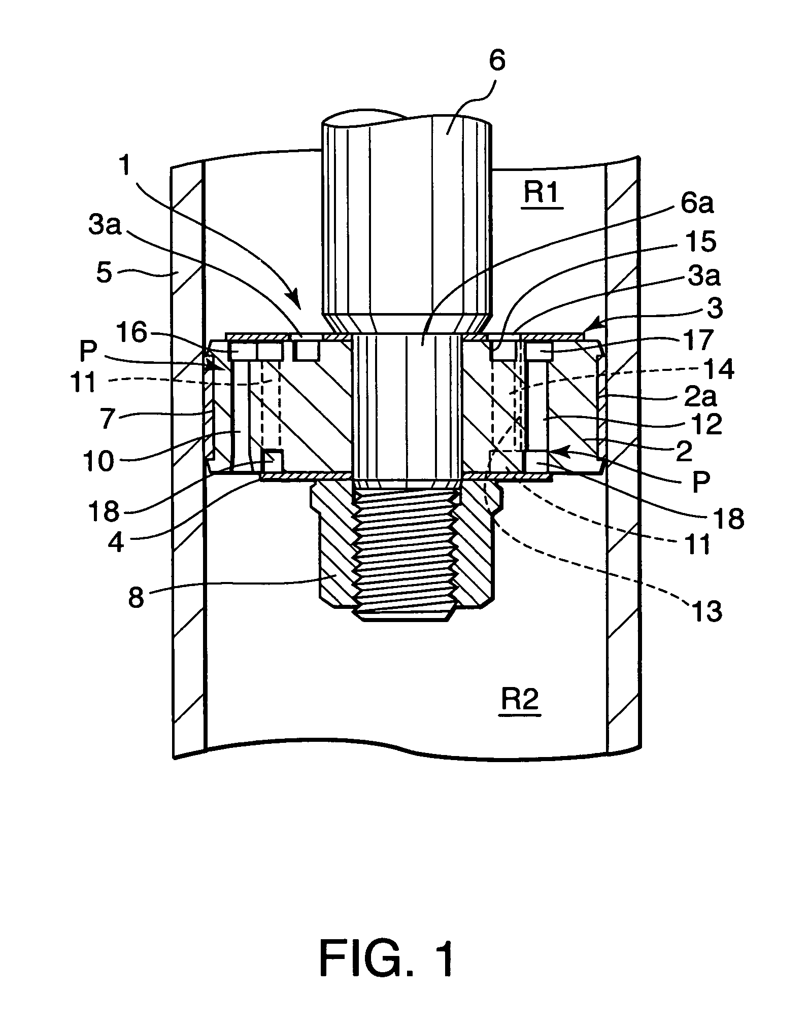
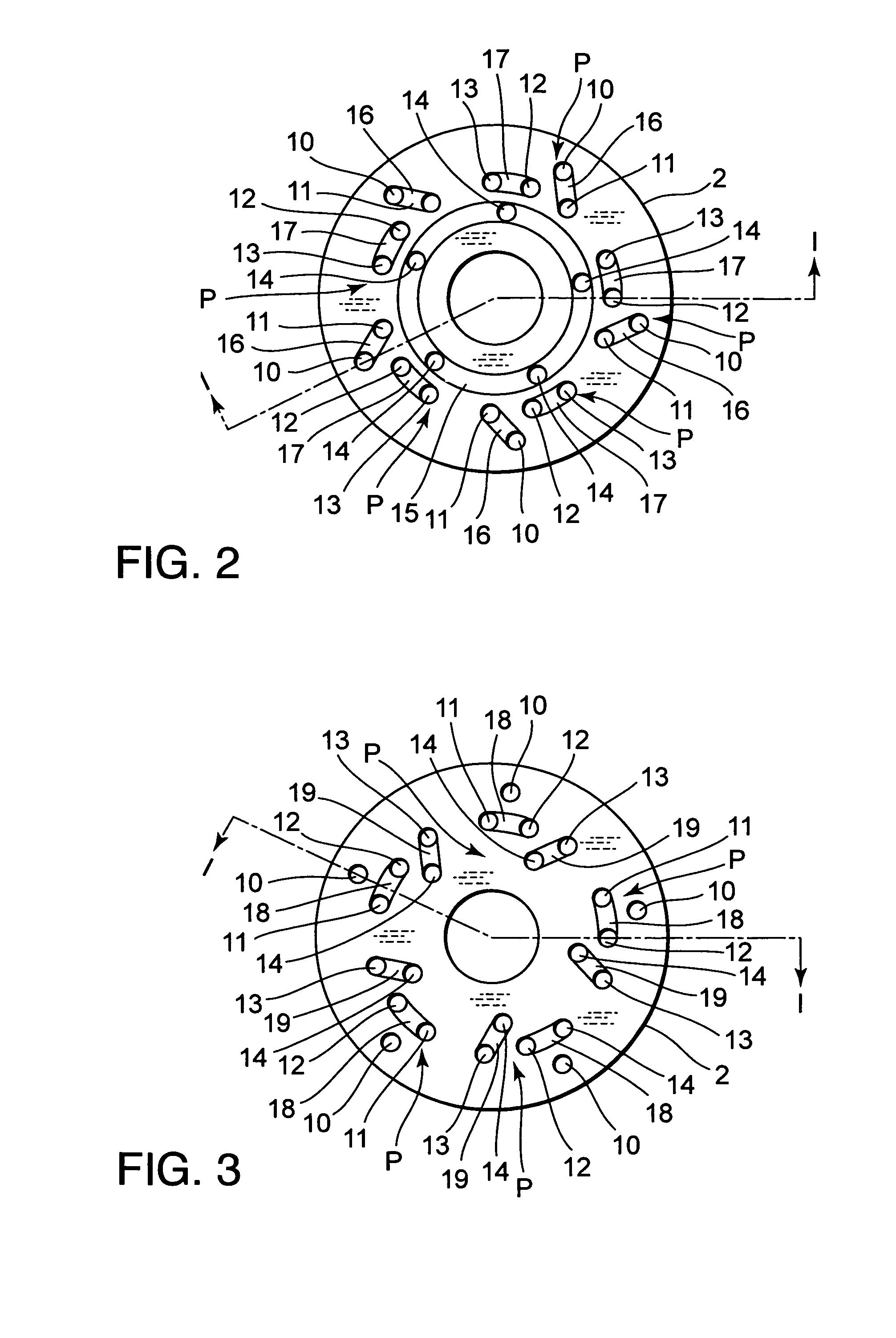
[0018]Referring to FIG. 1 of the drawings, a damping mechanism 1 according to this invention is applied to a piston 2 of a hydraulic shock absorber. The piston 2 is a disk-like member accommodated in a cylinder 5 filled with working fluid so as to be free to slide. A tip of a piston rod 6 is fixed to the piston 2. Another tip of the piston rod 6 projects from the cylinder 5 in an axial direction. The piston 2 separates the cylinder 5 into a first liquid chamber R1 around the piston rod 6 and a second liquid chamber R2 on the opposite side of the piston 2 to the piston rod 6. The piston 2 thus functions as a partitioning member for separating the first liquid chamber R1 from the second liquid chamber R2.

[0019]An annular groove 2a is formed in an outer periphery of the piston 2. A piston ring 7 is fitted in the annular groove 2a so as to contact an inner periphery of the cylinder 5. If the piston 2 is formed from a material suited for sliding on the inner periphery of the cylinder 5 s...


PUM


Abstract

A damping mechanism (1) that generates a damping force in response to a liquid flow between a first liquid chamber (R1) and a second liquid chamber (R2) comprises a partitioning member (2) separating the first liquid chamber (R1) and the second liquid chamber (R2) and a flow passage (P) formed in the partitioning member (2) to connect the first liquid chamber (R1) and the second liquid chamber (R2). The flow passage (P) comprises an odd number of through-holes (10-14) greater than three which penetrate the partitioning member (2) and are connected in series. A large amount of frictional energy loss due to a long path length occurs in the flow passage (P) and causes the damping mechanism (1) to generate a sufficient damping force.

Description

FIELD OF THE INVENTION[0001]This invention relates to a damping mechanism for a hydraulic shock absorber or the like.BACKGROUND OF THE INVENTION[0002]JP 2006-194335 A, published by the Japan Patent Office in 2006, proposes a damping mechanism for a hydraulic shock absorber, comprising a leaf valve constituted by plural leaves accumulated on an outlet of a port which is formed through a piston and a supporting member which supports a specific portion of the leaf valve in an axial direction. A central portion of the leaf valve is fixed to the piston and an outer peripheral part of the leaf valve is caused to lift as a pressure in the port increases, thereby opening the port.[0003]When the piston strokes in a direction opposite to the lifting direction of the leaf valve, the outer peripheral part of the leaf valve is lifted from the piston in response to a hydraulic pressure acting on the leaf valve via the port. As the port opens, working fluid flows through the port. The leaf valve g...

Claims


Application Information

Patent Timeline
Patent Type & Authority Patents(United States)
IPC IPC(8): F16F9/52
CPCF16F9/3481
Inventor MORITA, YUJI
Owner KYB CORP
Why Eureka
Try Eureka