
Electrical connection device between a pin-typed IC package and a circuit board

a technology of electrical connection device and pin-typed ic package, which is applied in the direction of coupling device connection, coupling device details, coupling contact members, etc., can solve the problems of easy twisted and damaged, poor electrical characteristic, and poor structural strength of connection, so as to increase production efficiency and production yield

Active Publication Date: 2005-08-16
VIA TECH INC
View PDF7 Cites 7 Cited by
  • Summary
  • Abstract
  • Description
  • Claims
  • Application Information

AI Technical Summary

Benefits of technology

[0007]The main objective of the invention is to provide an electrical connection device, wherein by the appropriately structural design of a conductive holder, the electrical connection device can provide preferable electric characteristic and co-planarity between the electrical connection part at the lower end of the holder and a circuit board to increase production efficiency, and production yield.
[0008]The secondary objective of the invention is to provide an electrical connection device, wherein by filling a resin material in the electrical connection part arranged at the lower end of the holder, the electrical connection device can provide preferable structural strength between the holder and a circuit board.

Problems solved by technology

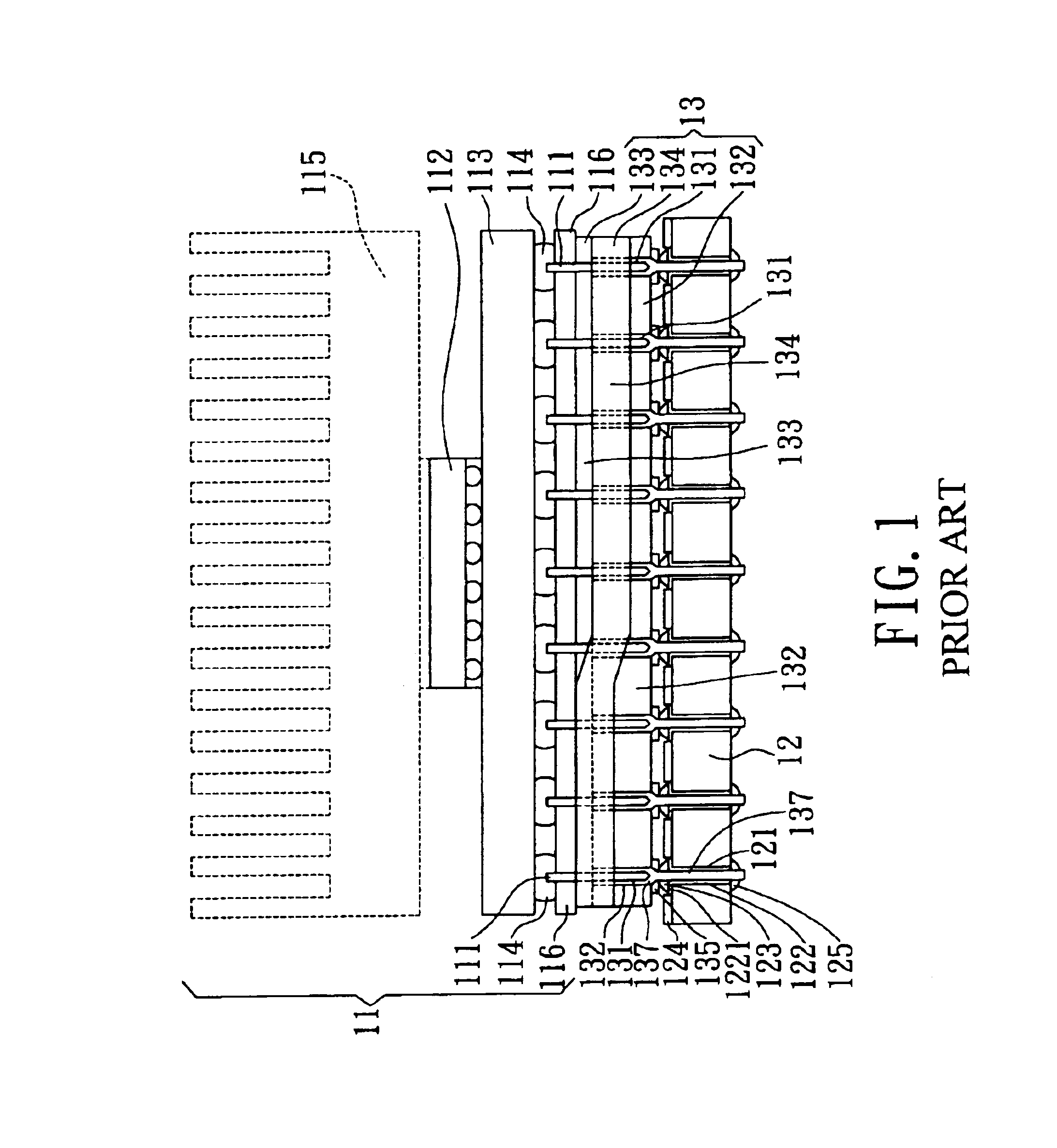
Since the pin 111 is not an object with extremely high rigidity, so it is easily twisted and damaged during the plugging and pulling procedures.
Therefore, the electric characteristic is relatively poor because of small contact surface, and the structural strength of connection is also relatively poor.
In the hot welding process, the material of solder ball 138 is overflowed to cause short circuit and electric unsteadiness.

Method used


Image

  • Electrical connection device between a pin-typed IC package and a circuit board
  • Electrical connection device between a pin-typed IC package and a circuit board
  • Electrical connection device between a pin-typed IC package and a circuit board

Examples


Embodiment Construction

[0021]Several preferable embodiments are proposed thereinafter to describe the detailed means, action manners, achievable functions, and other technical characteristics of the electrical connection device and its using method according to the invention in detailed way.

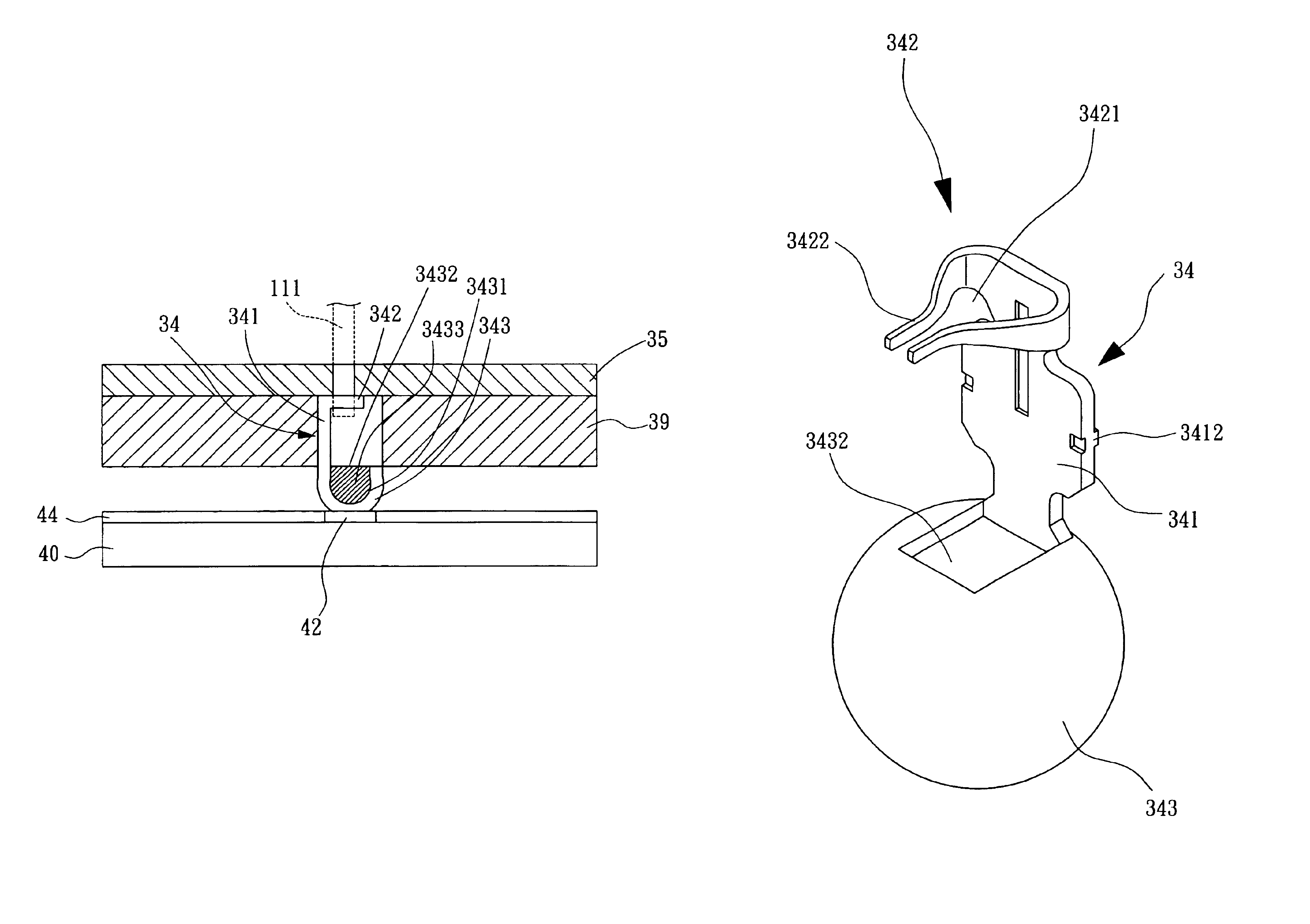
[0022]Please refer to FIG. 5, FIG. 6, and FIG. 7, which are side view illustrations for the first preferable embodiment of the electrical connection device 30 according to the invention. The electrical connection device 30 is applicable to an electric connection between a pin-typed IC package 11 and a circuit board 40 (or so-called main board), both of which are separable. In the preferable embodiment according to the invention, the IC package 11 has several pins 111, structure of which is same as that of prior arts which is not technical characteristic of the invention, so the detailed construction of an IC package 11 is not described herein, and only the contour of its outer appearance drawn by broken lines is roughl...


PUM


Abstract

An electrical connection device comprises a socket and a plurality of holders. A plurality of pinholes arranged on the socket provide a plug-in function for a plurality of pins of an IC device. A conductive holder placed in the pinhole is a single element made integrally by bending a metallic piece. The holder includes: an extension part arranged along the extension direction of pin-hole, a holding part located at the top end of the extension part, and an electrical connection part located at the bottom end of the extension part. The electrical connection part is a hollow structure having an accommodation inner space. The electrical connection part has a pouring opening so that the hollow structure may be filled with resin.

Description

[0001]This Nonprovisional application claims priority under 35 U.S.C. §119(a) on Patent Application No. 91215898 filed in TAIWAN on Oct. 8, 2002, the entire contents of which are hereby incorporated by reference.FIELD OF THE INVENTION[0002]The invention relates to an electrical connection device, and in particular, to a structural improvement for an electrical connection device that provide an electrical connection between a pin-type IC device and a circuit board.BACKGROUND OF THE INVENTION[0003]Since long time ago, there are two kinds of traditional manner to place integrated circuit package (abbreviated as IC package) on a circuit board (or called main board): one manner is directly welding wherein the IC package can not be pulled out, and another manner is replaceable wherein the IC package can be pulled out. The replaceable assembly device of an electrical connection device and a circuit board is usually adapted for IC package that needs upgrade or renew. And, when one of the ci...

Claims


Application Information

Patent Timeline
Patent Type & Authority Patents(United States)
IPC IPC(8): H01R13/115H01R13/02H01R13/193H01R12/00H01R12/16H01R13/11
CPCH01R13/193H01R12/7076H01R13/111Y10S439/936
Inventor KUNG, MORISSHO, KWUN-YAO
Owner VIA TECH INC
Learn More