Supercharge Your Innovation With Domain-Expert AI Agents!

Retardation compensating plate to compensate residual retardation of a liquid crystal panel, a compensator, a liquid crystal display device, and a projection image display apparatus having the same

a liquid crystal panel and residual retardation technology, applied in the field of retardation compensation plates, can solve the problems of difficult stably adjusting contrast, difficult to optimize contrast, and difficult to compensate residual retardation, so as to achieve flexible adaptation of residual retardation variations among individual liquid crystal panels, the effect of easy adjustment of contras

Active Publication Date: 2011-09-13
SONY CORP
View PDF14 Cites 4 Cited by
  • Summary
  • Abstract
  • Description
  • Claims
  • Application Information

AI Technical Summary

Benefits of technology

This solution allows for stable and flexible contrast adjustment, accommodating variations among liquid crystal panels with high accuracy, reducing the need for precise rotation adjustments and enhancing the overall contrast performance of the display apparatus.

Problems solved by technology

However, since the rotation of the plane of polarization caused by pretilting varies among liquid crystal panels, the residual retardation to be compensated varies among the liquid crystal panels.
In addition, because variations in the angle of placing another optical part are present, it is difficult to stably adjust the contrast merely by placing the quarter wave plate between the liquid crystal panel and the polarizing plate.
Therefore, the contrast optimization is difficult.

Method used


Image

  • Retardation compensating plate to compensate residual retardation of a liquid crystal panel, a compensator, a liquid crystal display device, and a projection image display apparatus having the same
  • Retardation compensating plate to compensate residual retardation of a liquid crystal panel, a compensator, a liquid crystal display device, and a projection image display apparatus having the same
  • Retardation compensating plate to compensate residual retardation of a liquid crystal panel, a compensator, a liquid crystal display device, and a projection image display apparatus having the same

Examples


examples

[0158]Examples of the present invention are describe below. The present invention is not limited to these examples.

examples 1 to 4

[0159]The amount of compensated retardation with respect to the liquid crystal panel when the slow axis of a retardation compensating plate according to the examples and comparative examples is rotated was measured as follows. The rotations were performed clockwise using as 0 degrees an angle at which the slow axis R1 of the liquid crystal panel matches the slow axis R2 of the retardation compensating plate (see FIGS. 8 and 9). The in-plane retardation (R0p) of the liquid crystal panel was determined as 2.5 nm.

example 1

[0160]A retardation compensating plate having an in-plane retardation (R0c) of 12 nm was prepared. The changes occurring when the slow axis R2 of the retardation compensating plate was rotated with respect to the slow axis R1 of the liquid crystal panel were measured (R0c / R0p=4.8).


PUM

PropertyMeasurementUnit
glass transition pointaaaaaaaaaa
thicknessaaaaaaaaaa

Abstract

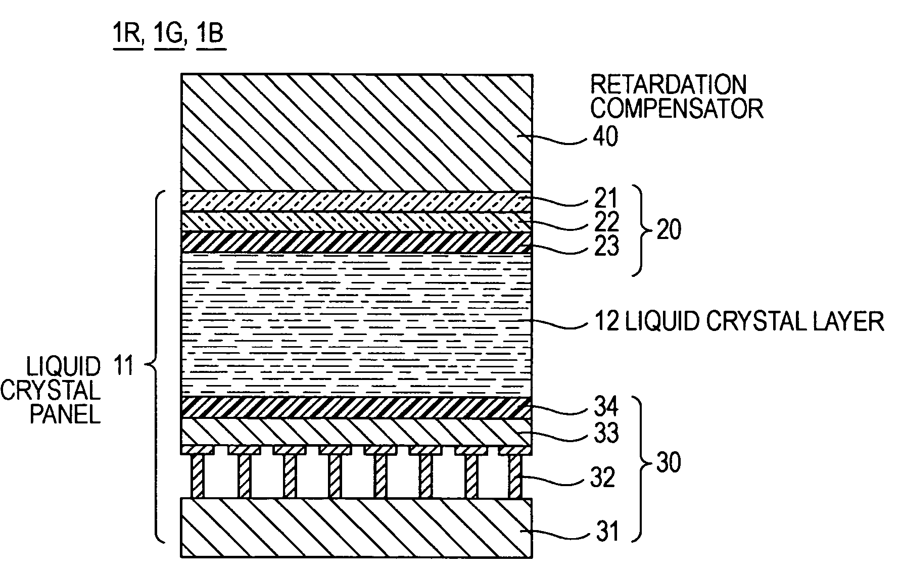
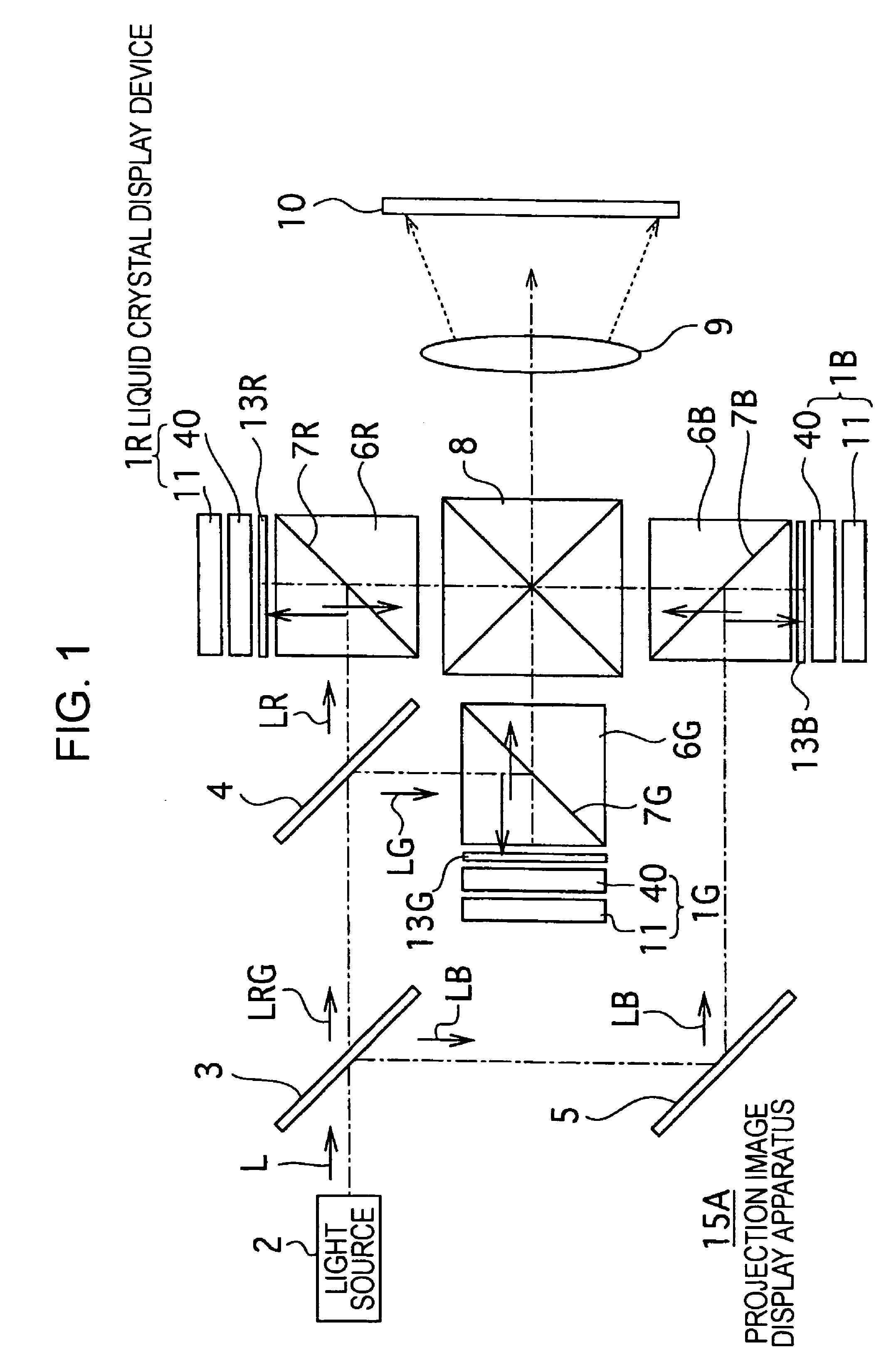
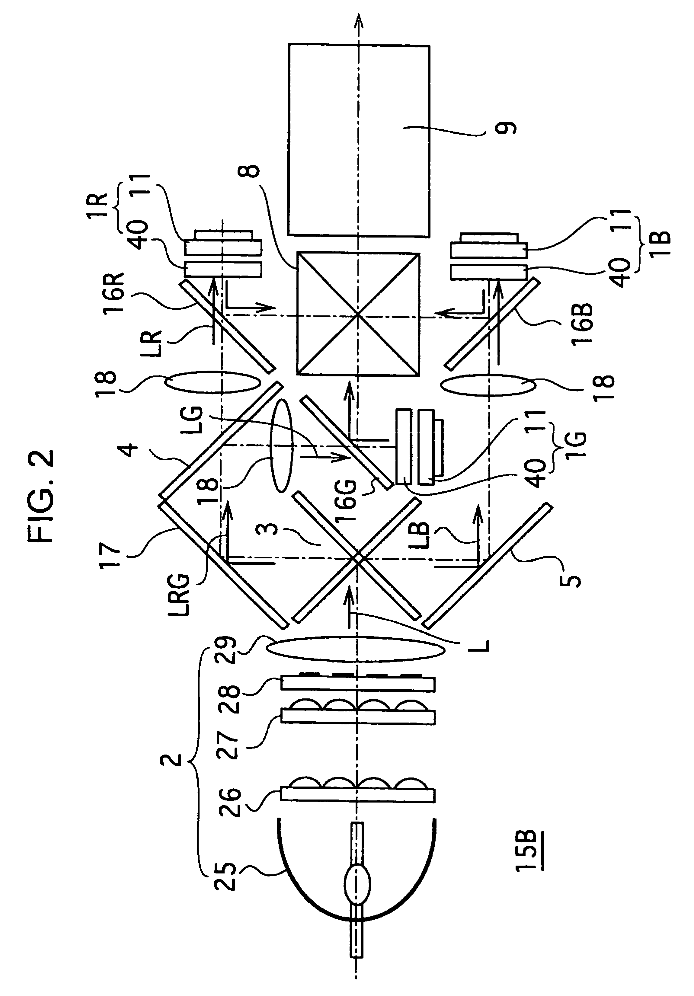
A retardation compensator 40 for compensating for residual retardation of a liquid crystal panel 11 includes a retardation compensating plate 50 having birefringence. An in-plane retardation R0c of the retardation compensating plate 50 and an in-plane retardation R0p of the liquid crystal panel 11 satisfy a relationship of 1<R0c / R0p≦10, thereby allowing changes in the amount of compensated retardation among rotation angles occurring when the retardation compensating plate 50 is set with respect to the liquid crystal panel 11 to be confined within narrow limits. Therefore, the contrast can be adjusted readily, and variations in residual retardation among the individual liquid crystal panels 11 can be accommodated flexibly.

Description

CROSS REFERENCES TO RELATED APPLICATIONS[0001]The present invention contains subject matter related to Japanese Patent Application Nos. 2005-074136 filed in the Japanese Patent Office on Mar. 15, 2005, 2005-163757 filed on Jun. 3, 2005, and 2006-064965 filed on Mar. 9, 2006, the entire contents of which are incorporated herein by reference.TECHNICAL FIELD[0002]The present invention relates to a retardation compensation plate used for retardation compensation for, for example, a liquid crystal panel, a retardation compensator employing the retardation compensation plate, a liquid crystal display device, and a projection image display apparatus.BACKGROUND OF THE INVENTION[0003]A projector, which achieves a large screen display by projecting an enlarged image onto a screen, has conventionally been known as a projection image display apparatus. Recently, in particular, a so-called liquid crystal projector, which optically modulates light emitted from a light source by using a liquid cry...

Claims


Application Information

Patent Timeline
Patent Type & Authority Patents(United States)
IPC IPC(8): G02F1/1335
CPCG02B5/3083G02F1/133634G02F1/1335G02F1/13363
Inventor MURAMOTO, YUTAKASEKINO, SATOSHITERASHIMA, HIDEKIHARIMA, TATSUYASHOJI, SACHIEDOI, NORIAKIMORIOKA, TOKUHIRO
Owner SONY CORP
Features
  • R&D
  • Intellectual Property
  • Life Sciences
  • Materials
  • Tech Scout
  • Unparalleled Data Quality
  • Higher Quality Content
  • 60% Fewer Hallucinations
Learn More