
Agricultural harvesting machine

a harvesting machine and agricultural technology, applied in the field of agricultural harvesting machines, can solve the problems of difficult estimation of whether even experienced operators are capable, ineffective prediction, and a large amount of time is required to optimize the operating parameters, and achieve the effect of reliable prognosis

Active Publication Date: 2011-09-13
CLAAS SELBSTFAHRENDE ERNTEMASCHINEN GMBH
View PDF14 Cites 18 Cited by
  • Summary
  • Abstract
  • Description
  • Claims
  • Application Information

AI Technical Summary

Benefits of technology

[0006]The object of the present invention, therefore, is to avoid the disadvantages of the related art mentioned above, and, in particular, to refine an agricultural harvesting machine in a manner such that it easily provides the operator with a reliable prognosis during the on-going harvesting process as to which harvesting goal is attainable at the end of the harvesting process chain using the selected operating parameters, thereby ensuring that the prognosis may be taken into account when the operating parameters are adjusted as necessary.
[0010]An extremely accurate prognosis regarding the attainability of an actual harvesting goal is obtained when the set harvesting goal is based on expert knowledge which has been obtained, e.g. based on a large number of tests carried out at a testing installation, and is therefore statistically confirmed. It is also feasible for the expert knowledge to be based on knowledge that was obtained via a large number of actual harvesting results, or on knowledge obtained from many operators of machines that are used in the harvesting process. Advantageously, the set harvesting goal which is based on expert knowledge is stored in the memory and evaluation unit in the form of at least one characteristic curve, thereby making it possible to formulate the prognosis regarding the attainable actual harvesting goal very rapidly for different harvesting conditions, based on the comparison with the current operating parameters and crop material parameters.

Problems solved by technology

Since other vehicles are used in the harvesting process chain in addition to the harvesting machines, e.g. hauling vehicles and compacting vehicles in the silo, very complex interrelationships exist between the vehicles involved in the harvesting process and their influence on the desired harvesting goal to be attained at the end of the harvesting process chain, such as the desired level of compaction of crop material in a silo, thereby making it difficult even for experienced operators to estimate whether the operating parameters he selected will actually result in the desired harvesting goal being attained.
In particular, the comparison that is used, i.e. a comparison of an actual value of individual operating parameters with a setpoint value (=ideal value) for the particular operating parameter, is not very effective in predicting whether or not a desired harvesting goal will be attained at the end of the harvesting process chain.
The disadvantage of this method is that, due to the time delay between the particular start of the harvesting operation and the instant when the working result is attained, a great deal of time is required to optimize the operating parameters.
It is also disadvantageous that the operator must repeatedly try to attain a nearly constant crop material throughput rate in order to ensure that the working results obtained using different operating parameters may be compared with one another.
However, it is not possible to make a reliable prognosis as to whether a desired harvesting goal is attainable.
This requires a great deal of experience and ability on the part of the operator, and it requires a great deal of time.
However, neural networks having large capacity require a level of computational ability that is practically unaffordable.
Given the current status of development of neural network techniques, large neural networks have limited practical utility in harvesting machine applications.

Method used


Image

  • Agricultural harvesting machine
  • Agricultural harvesting machine
  • Agricultural harvesting machine

Examples


Embodiment Construction

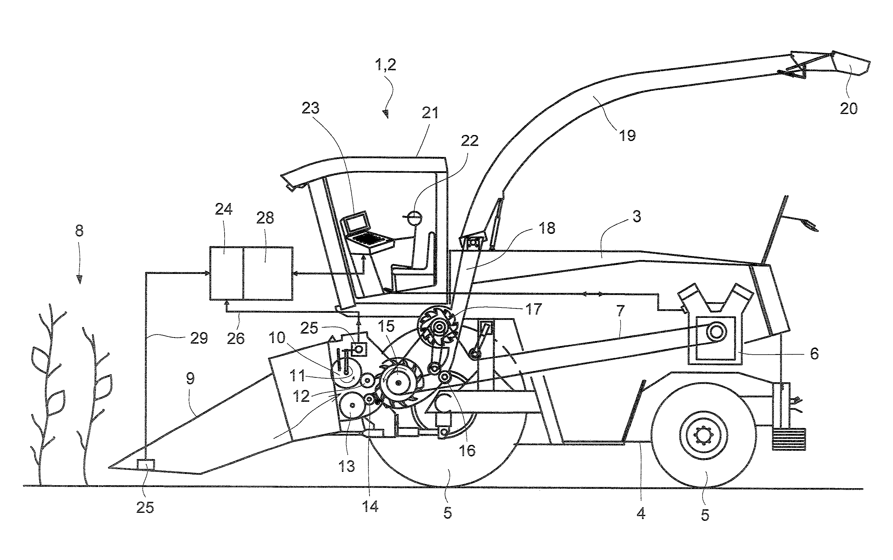
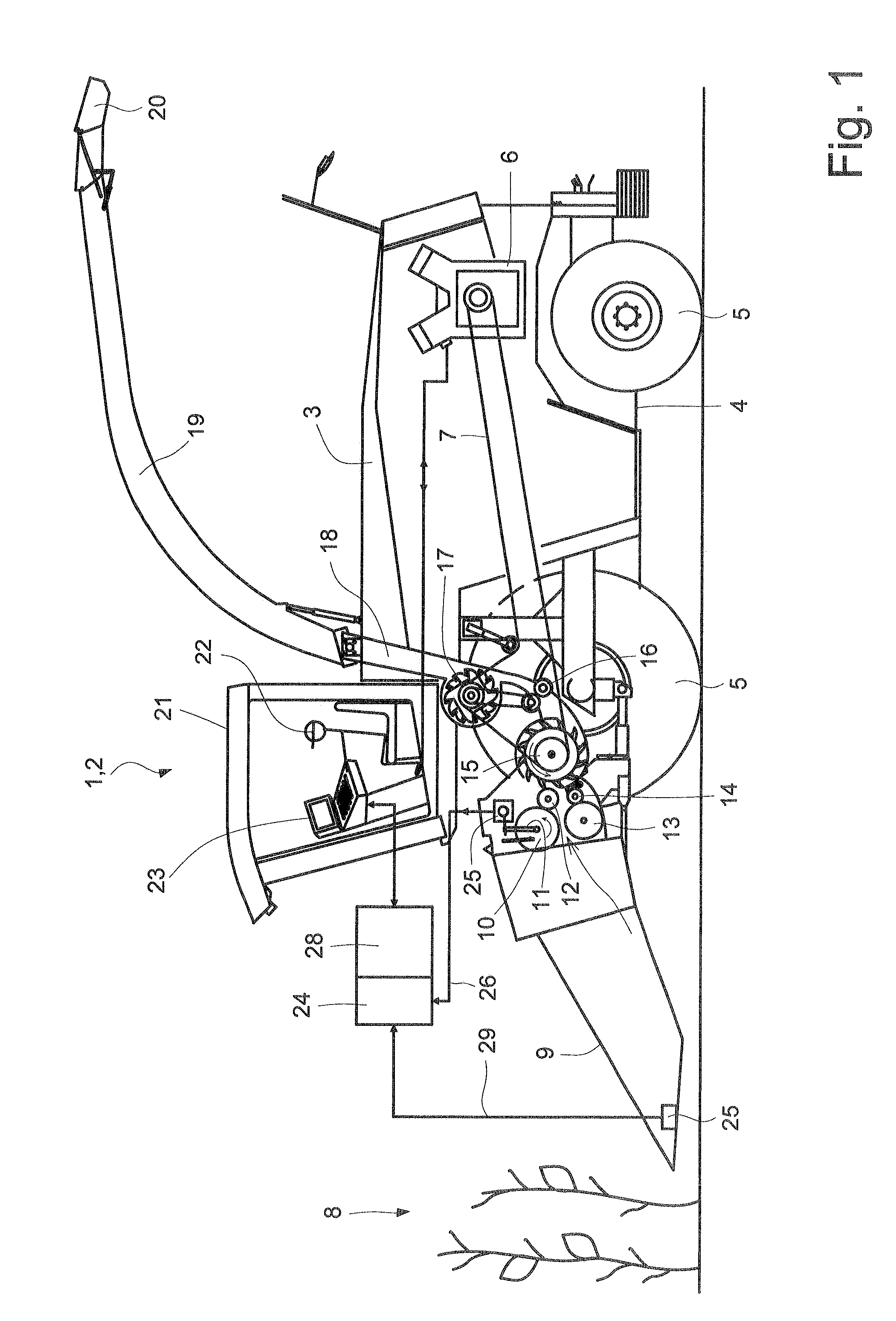
[0020]Agricultural harvesting machine 2 which is designed as a forage harvester 1 and is shown in a partially exposed side view in FIG. 1, includes a housing 3 and a ground drive 4 on which wheels 5 are situated. An engine 6 is used as the drive, and is connected via a belt 7 to the working units of forage harvester 1.

[0021]Crop material 8 to be harvested is cut and picked up using a front attachment 9. Front attachment 9 is followed directly by intake device 10 which, in this embodiment, includes two lower intake and compression rollers 11, 12, and two upper intake and compression rollers 13, 14 which are situated on a frame or housing 3.

[0022]To ensure that a defined length of cut of crop material 8 is attained in the harvesting process, the feed speeds of forage harvester 1 are continually increased along the path of crop material 8 through harvesting machine 2. This means that intake and compression rollers 11, 12, 13, 14 are driven at a lower circumferential speed than is chopp...


PUM


Abstract

An agricultural harvesting machine includes different working units, an input and display unit, a memory and evaluation unit, and a control device for influencing adjustable operating parameters of the working units, at least one set criterium being stored in the memory and evaluation unit, and, based on at least one crop material parameter and / or operating parameter that was determined in the harvesting process, and based on the at least one set criterium, a prognosis regarding the attainability of an actual harvesting goal is formulated, the prognosis being taken into account in the adjustment of the operating parameters.

Description

CROSS-REFERENCE TO A RELATED APPLICATION[0001]The invention described and claimed hereinbelow is also described in German Patent Application DE 10 2008 027 906.4 filed on Jun. 12, 2008. This German Patent Application, whose subject matter is incorporated here by reference, provides the basis for a claim of priority of invention under 35 U.S.C. 119(a)-(d).BACKGROUND OF THE INVENTION[0002]The present invention relates to an agricultural harvesting machine.[0003]For the operator of a harvesting machine, it is imperative that the parameters of the machine components be set correctly in order to ensure that a harvesting process is attained that reaches a desired harvesting goal to be attained at the end of the harvesting process chain. As a result, it is now common when harvesting grass or corn for silage, for instance, for the operator to set operating parameters, e.g. the length of cut, before and while working a field. The operator relies largely on experience when setting the operati...

Claims


Application Information

Patent Timeline
Patent Type & Authority Patents(United States)
IPC IPC(8): A01D41/127
CPCA01D41/127A01D43/085
Inventor BOENIG, INGOHAFFERT, ANDREAS
Owner CLAAS SELBSTFAHRENDE ERNTEMASCHINEN GMBH
Learn More