Radiant mat grid

a technology of radiant mats and grids, applied in the direction of fluid heaters, heating types, lighting and heating apparatuses, etc., can solve the problems of inability to hold securely, inhibit heat transfer, and reduce efficiency

Inactive Publication Date: 2011-09-20
BACKMAN JR JAMES JOSEPH
View PDF54 Cites 37 Cited by
  • Summary
  • Abstract
  • Description
  • Claims
  • Application Information

AI Technical Summary

Benefits of technology

The invention described herein is an improved method of attaching heated or cooled liquid filled molecularly crossed linked polyethylene tubing other tubing or electrical heating cables to a floor, wall or ceiling to create a heating or cooling radiant panel. The invention described herein in one of it's preferred embodiments allows for a complete modular system that can be disassembled and reassembled at will.

Problems solved by technology

1) The tubes are not held securely and therefore they tend to pop out of their matrix or mat during the overpouring;
2) When Polystyrene or other foam based tube holding matrices are used, the entire system is up to three times as thick as the present invention;
3) Current systems use knobs or integrated insulation systems which inhibit heat transfer and are less efficient;
4) Prior systems are prone to damage during the overpour process. The present invention is much less prone to damage prior to and during the overpour.
5) Current systems are not as modular and require more cutting and waste;
6) Current systems do not lock together as effectively or completely and the current invention is able to allow pre-staging of larger sheets of mats or grids then other existing systems;
7) Current systems do not lay as flat and uniform as the present invention;
8) Current systems do not bear weight as effectively as the present invention;
9) Current systems constructed of vacuum formed or heat stamped polystyrene or other similar materials have little inherent structural integrity, do not lay as flat, and tend to create an insulated knob, thereby inhibiting lateral heat transfer;
10) Current systems do not have a recessed anchor point to accept and guide a screw or other fastening device to anchor the mat to the floor, walls or ceiling;
11) Current systems do not have a recessed anchor point to accept and guide into place a top layer constructed of cement board, wood, cellulose, plastic composite, aluminum, copper or other structural and heat diffusion aiding material creating an integrated modular system that can be completely installed, uninstalled, and then re-assembled;
12) Current systems do not allow for the addition of a combination top layer comprised of an anti-fatigue mat, a shop floor, and / or transition ramps to a concrete shop floor for use in modular industrial applications.
13) Current systems do not allow for the overpour material to penetrate the attaching knob and consequently do not add any structural benefits to the overpour situation or aid in heat transfer.
14) Current systems do not allow for the integration of finish floor products made of wood, tile, stone, linoleum, metal, etc.

Method used


Image

  • Radiant mat grid
  • Radiant mat grid
  • Radiant mat grid

Examples


Embodiment Construction

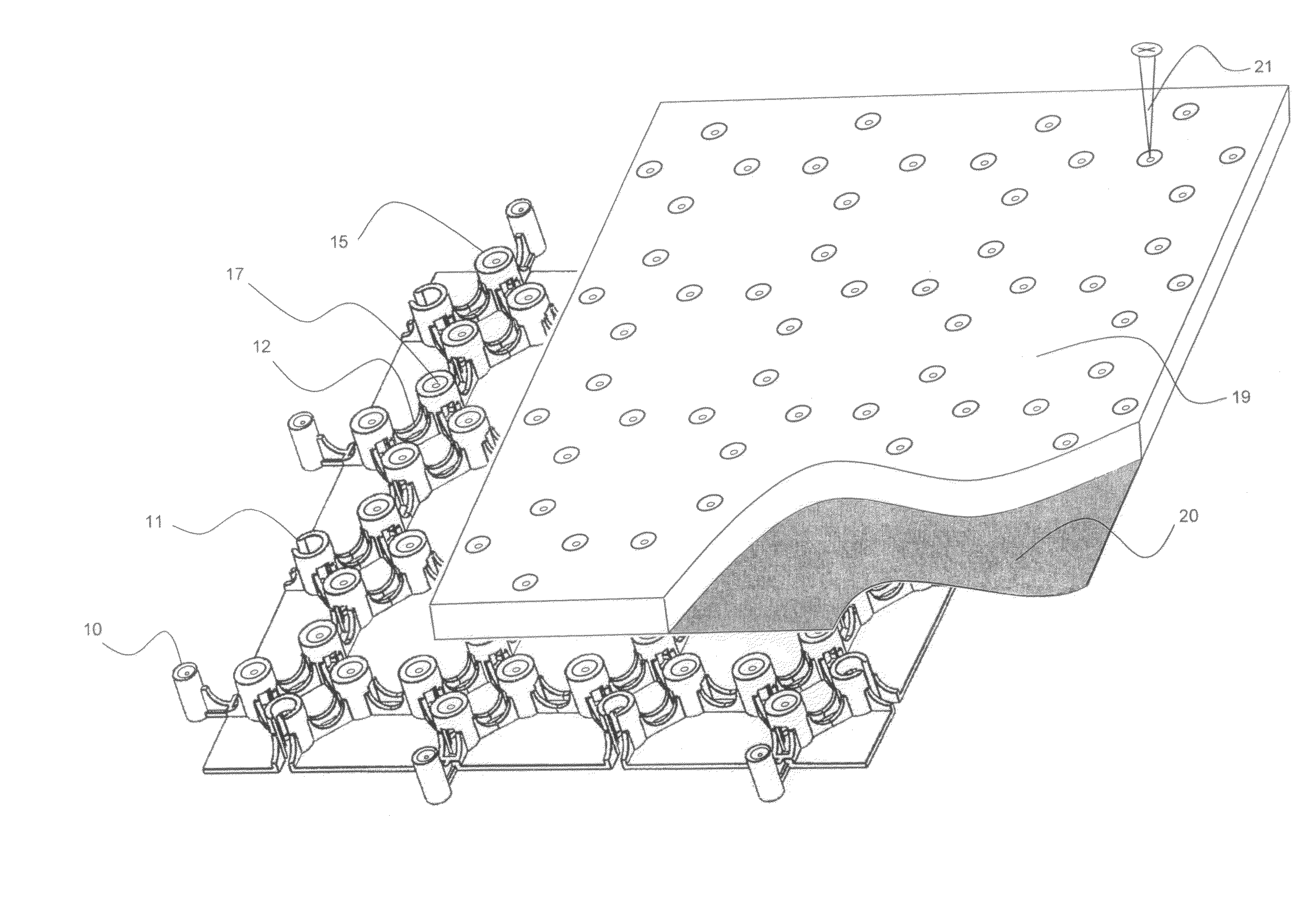
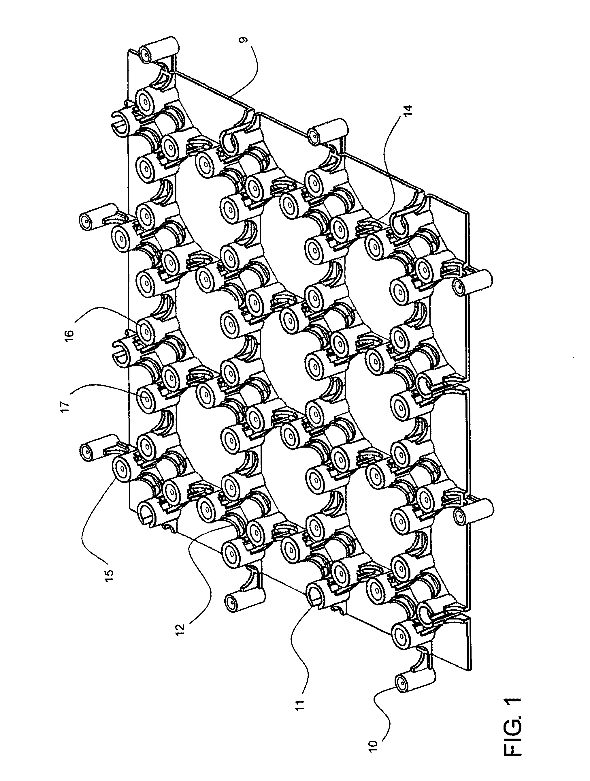
A single radiant Mat Grid tile (9) has an upper surface and a lower surface. There are a plurality of protuberances (10) extending beyond the perimeter of the radiant Mat Grid (9) around its circumference. Each protuberance or male knob (10) can snap securely into a corresponding protuberance receptacle or female knob (11) placed along the interior of the circumference of a neighboring tile. Each separate tile is snapped together with other tiles creating a monolithic Radiant Mat Grid matrix. The interior of each tile contains a plurality of weight bearing support knobs (15) on its upper surface. Each weight bearing support knob (15) has a recess at the upper end (16) and a screw guide opening (17) together comprising a screw recess unit. Each weight bearing support knob (15) can be used to mate with an additional top layer. A screw or other fastener means can be inserted through each screw guide unit via the screw guide hole (17) inside each weight bearing support knob (15) to atta...


PUM


Abstract

An improved apparatus and method of attaching heated or cooled liquid filled tubing to a floor, wall or ceiling to create a radiant heating or cooling system.

Description

STATEMENT REGARDING FEDERALLY SPONSORED RESEARCH FOR DEVELOPMENTNo Federal Funds were used in the development of this Invention.THE NAMES OF THE PARTIES TO A JOINT RESEARCH AGREEMENTNot Applicable.INCORPORATION-BY-REFERENCE OF MATERIAL SUBMITTED ON A COMPACT DISCNot Applicable.BACKGROUND OF THE INVENTIONRadiant floor heating systems have been in use commercially and in residential structures since the Roman Times. Low temperature radiant panels are the most effective method of heating and cooling transfer known. The Radiant Panel Association claims 20% to 40% more efficiency in a heating application than forced air type heating. Radiant heating and cooling is completely clean and silent with no dust, allergens or pollutants blowing around the structure. Radiant heating and cooling offers complete interior design flexibility as there are no ducts or registers to accommodate. Frank Lloyd Wright and others designed many in the early twentieth century using copper tubing and iron piping...

Claims


Application Information

Patent Timeline
Patent Type & Authority Patents(United States)
IPC IPC(8): F24D3/12F24D3/16E04F11/16
CPCF24D3/142Y02B30/00
Inventor BACKMAN, JR., JAMES JOSEPH
Owner BACKMAN JR JAMES JOSEPH
Why Eureka
Try Eureka